Rotary transformer and rotating body equipped with same

A rotary transformer and rotary body technology, applied in the field of transformers and rotary bodies, rotary transformers and rotary bodies, can solve problems such as increased risk of connection line failure, rotary transformer failure, complex manufacturing process, etc., to improve rapid response performance and prevent unfavorable Influencing and simplifying the production process

Pending Publication Date: 2017-05-10
苏州昱泽智能科技有限公司
View PDF0 Cites 5 Cited by
  • Summary
  • Abstract
  • Description
  • Claims
  • Application Information

AI Technical Summary

Problems solved by technology

However, the current resolver has many disadvantages: the existing resolver has reached the limit of miniaturization and light weight, and it is difficult to break through the current bottleneck; the stator detection teeth are wound with multiple sets of windings, usually three sets of windings, The manufacturing process is very complicated, and the consistency of the resolver is adversely affected due to the different positions of the windings; since there are multiple sets of windings on the stator detection teeth, it is easy to appear between different windings due to vibration and shock during use. Problems such as short circuit and disconnection will

Method used


Image

  • Rotary transformer and rotating body equipped with same
  • Rotary transformer and rotating body equipped with same
  • Rotary transformer and rotating body equipped with same

Examples


no. 1 example

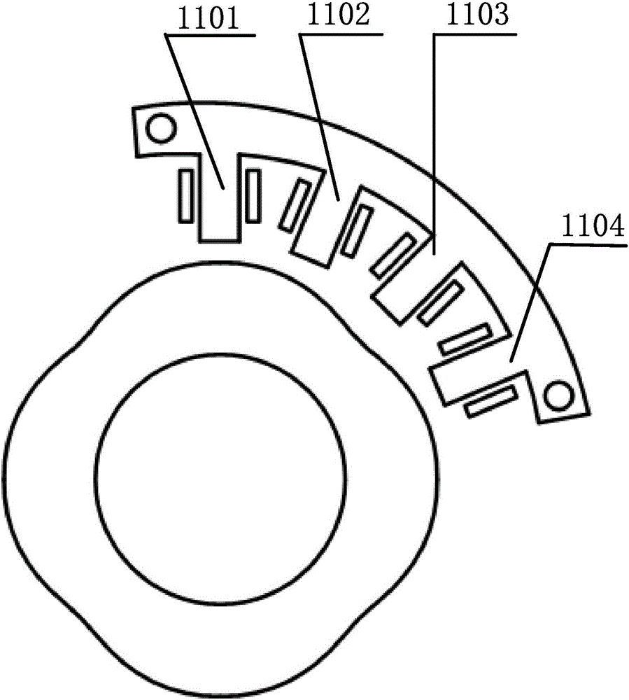
[0047] In this embodiment, K=1 and N=4, so the number of stator detection teeth of the resolver is 4, and the number of salient poles of the rotor is 4. figure 1 Shown is a schematic cross-sectional view of the stator and rotor of the resolver. The stator includes a stator yoke and stator detection teeth, the stator detection teeth are arranged on the stator yoke; the angle spanned by the stator yoke is less than 360 degrees, and the rotor includes a rotor core. Both the stator core and the rotor core are formed by stamping silicon steel sheets. In this embodiment, the 4 salient rotor poles are evenly distributed along the circumference of the rotor core surface, the 4 stator detection teeth are distributed along the circumferential surface of the stator yoke, and the 4 stator detection teeth are distributed clockwise along the circumference as 1101, 1102, 1103, 1104. The included angle between stator detection tooth 1101 and stator detection tooth 1102 is 22.5 degrees, the in...

no. 2 example

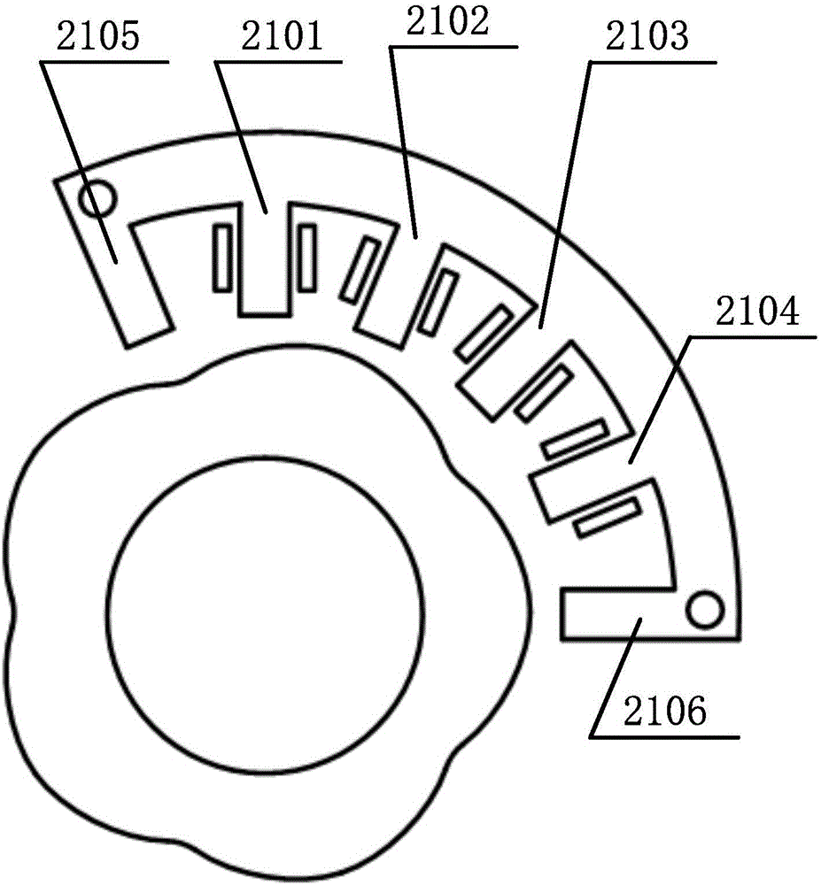
[0070] In this embodiment, K=1 and N=5, so the number of stator detection teeth of the resolver is 4, and the number of salient poles of the rotor is 5. image 3 Shown is a schematic cross-sectional view of the stator and rotor of the resolver. The stator includes a stator yoke and stator detection teeth, the stator detection teeth are arranged on the stator yoke; the angle spanned by the stator yoke is less than 360 degrees, and the rotor includes a rotor core. Both the stator core and the rotor core are formed by stamping silicon steel sheets. In this embodiment, the five salient rotor poles are evenly distributed along the circumference of the rotor core surface. The 4 stator detection teeth are distributed along the circumferential surface of the stator yoke, and the 4 stator detection teeth are distributed clockwise along the circumference as 2101, 2102, 2103, 2104. The included angle between the stator detection teeth 2101 and the stator detection teeth 2102 is 18 degree...

no. 3 example

[0076] In this embodiment, K=1 and N=6, so the number of stator detection teeth of the resolver is 4, and the number of salient poles of the rotor is 6. Figure 4 Shown is a schematic cross-sectional view of the stator and rotor of the resolver. The stator includes a stator yoke and stator detection teeth, the stator detection teeth are arranged on the stator yoke; the angle spanned by the stator yoke is less than 360 degrees, and the rotor includes a rotor core. Both the stator core and the rotor core are formed by stamping silicon steel sheets. In this embodiment, the 6 salient rotor poles are evenly distributed on the circumference of the rotor core surface. The 4 stator detection teeth are distributed along the circumferential surface of the stator yoke, and the 4 stator detection teeth are distributed clockwise along the circumference as 3101, 3102, 3103, 3104. The angle between the stator detection teeth 3101 and the stator detection teeth 3102 is 15 degrees, the angle b...


PUM


Abstract

The invention provides a rotary transformer and a rotating body equipped with same, and belongs to the technical field of detection. The rotary transformer comprises a stator and a rotor, wherein the stator comprises a stator yoke and stator detection teeth, and the stator detection teeth are arranged on the stator yoke; the spanning angle of the stator yoke is smaller than 360 degrees; the rotor comprises a rotor iron core; rotor salient poles are arranged on the surface of the rotor iron core; the number of the stator detection teeth is 4*K, wherein K is a positive integer; the number of the rotor salient poles is N, wherein N is a positive integer; each stator detection tooth is at most wound with a coil; the rotary transformer comprises at least one set of detection coil system; each detection coil system comprises a plurality of coils wound around the stator detection teeth; inductance of the coils is changed along with changes of the rotating angles of the rotor; and the rotating body comprises a rotating body main body and the rotary transformer, wherein the rotary angle of the rotating body main body and the rotary transformer are in a regular relationship. The miniaturization and light weight of the rotary transformer are promoted; and in addition, winding and line connection are simpler and more effective.

Description

Technical field [0001] The invention belongs to the technical field of detection, and relates to a transformer and a rotating body, in particular a resolver and a rotating body. Background technique [0002] Industries such as electric vehicles, industrial automation, robotics, textile machinery, and aerospace are inseparable from the high-performance control of rotating electric machines, which require motor rotation angle sensors and often require them to be used in high-temperature environments. [0003] Currently, photoelectric angle encoders are widely used because they can easily detect the rotation angle of the motor. However, such photoelectric angle encoders contain optoelectronic components and semiconductor devices, so they cannot be used in high temperature environments. [0004] The resolver is a sensor that can detect the rotation angle. Because it does not use photoelectric conversion devices, it can be used in a higher temperature environment. However, the current re...

Claims


Application Information

Patent Timeline
IPC IPC(8): H02K24/00H02K1/24H02K1/14H02K3/28
CPCH02K1/14H02K1/24H02K3/28H02K24/00H02K2213/03
Inventor 高翔
Owner 苏州昱泽智能科技有限公司
Why Eureka
Try Eureka