Method and circuit for testing instantaneous currents of electric leakage protectors

A leakage protector and testing circuit technology, which is applied to the parts of electrical measuring instruments, using AC to DC for measurement, instruments, etc., can solve the problems of uncontrollable, unbalanced zero-sequence transformer 4, and high simulated leakage current value. , to achieve the effect of increasing miniaturization, testing stability, and increasing reliability

Pending Publication Date: 2017-05-31
许良炎
View PDF14 Cites 0 Cited by
  • Summary
  • Abstract
  • Description
  • Claims
  • Application Information

AI Technical Summary

Problems solved by technology

[0004] like figure 1 As shown, the current household leakage protector RCD has a normally open test button 7 (referred to as the test button here), and a current limiting resistor 6 in series, and their two ends are connected to the wiring of the input power supply 1 and the output power supply 5 of the leakage protector. Once the test button 7 is triggered, the 30mA analog leakage current flowing through the button and the resistor will increase the current difference between the live wire and the neutral wire in the leakage protector by 30mA, and the zero-sequence transformer 4 will be seriously unbalanced. The electrical signal is amplified by the amplifier 3, and its current flows into the electromagnetic coil of the uncoupling device 2 to generate a strong magnetic field. The pulling force of the magnetic field makes the decoupling device loosen the contact point carrying the power supply, and the leakage protector trips accordingly.
[0005] Once any test button of the existing leakage protector is pressed, the simulated leakage current will continue to flow until the test button is released, and the time length of the simulated leakage current follows the time length of the test button being pressed, which can be from 0.1 From 2 seconds to 2 seconds, or even longer, completely uncontrollable, so it cannot detect the tripping response sensitivity of the leakage protector
In order for the leakage protector to effectively drive the tripping action, the simulated leakage current value needs to be higher than 30mA, which causes the thermal power consumption to be at least 6.6W. Therefore, the circuit needs to use large and high-power resistors to prevent burnout, and installing large resistors is also necessary. need more space
like figure 2 As shown, once the second test button of the leakage protector is pressed, the simulated leakage current will continue to flow between the live wire and the neutral wire until the test button is released. In order to test the operation stability of the leakage protector, the simulated leakage current The value needs to be increased to about 15mA, which makes the thermal power consumption at least 3.3W. The circuit also needs to use large and high-power resistors to prevent burnout, and a large space is required to install large resistors.
[0006] like figure 2 The double test circuit shown cannot precisely control the duration of the leakage current generated by the first and second test circuits, and the duration of the simulated leakage current is completely determined by the time when the user manually presses the test button on site, which can be as long as several seconds
Therefore, pressing the first test circuit cannot let the user know whether his RCD can trip in 0.1 seconds or less

Method used


Image

  • Method and circuit for testing instantaneous currents of electric leakage protectors
  • Method and circuit for testing instantaneous currents of electric leakage protectors
  • Method and circuit for testing instantaneous currents of electric leakage protectors

Examples


Embodiment 1

[0049] Embodiment 1: The single-button instantaneous current test circuit of leakage protector uses a triode circuit

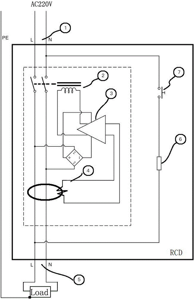
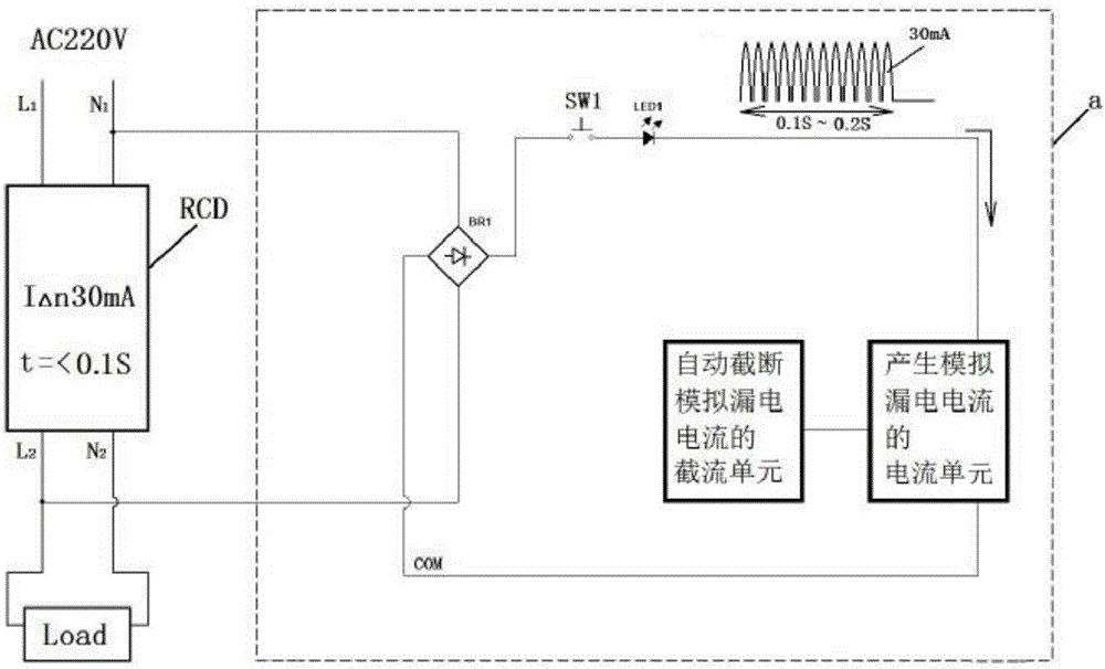
[0050] like image 3 , as shown in 5, the test circuit can generate an instantaneous tripping simulation leakage, its magnitude is greater than or equal to 30mA, and its short duration is between 0.1 and 0.2 seconds. The circuit structure includes a bridge rectifier BR1, its two AC input pins are connected to the neutral line N1 of the power input end of the leakage protector and the live wire L2 of the power output end of the leakage protector (or connected to the live wire L1 of the power input end of the leakage protector and the power output terminal neutral line N2 of the leakage protector), the negative (-) pin of BR1 is connected to the common loop point COM (also known as the common end, common connection point) of the entire circuit, and the positive (+) pin of BR1 is connected to the button SW1 One end of the (NO type), the other end of SW1 is conne...

Embodiment 2

[0052] Example 2: A single-button instantaneous current test circuit for a leakage protector uses a thyristor circuit

[0053] like image 3 , as shown in 8, the difference between this embodiment 2 and embodiment 1 is that the first triode Q1 in embodiment 1 is replaced by a thyristor D1, where R2=1.2MΩ, R7=20Ω, and the electrical components of other electronic components Parameters, wiring and principles between electronic components are the same as those in Embodiment 1.

Embodiment 3

[0054] Example 3: The double-key instantaneous current test circuit of the leakage protector uses a triode circuit

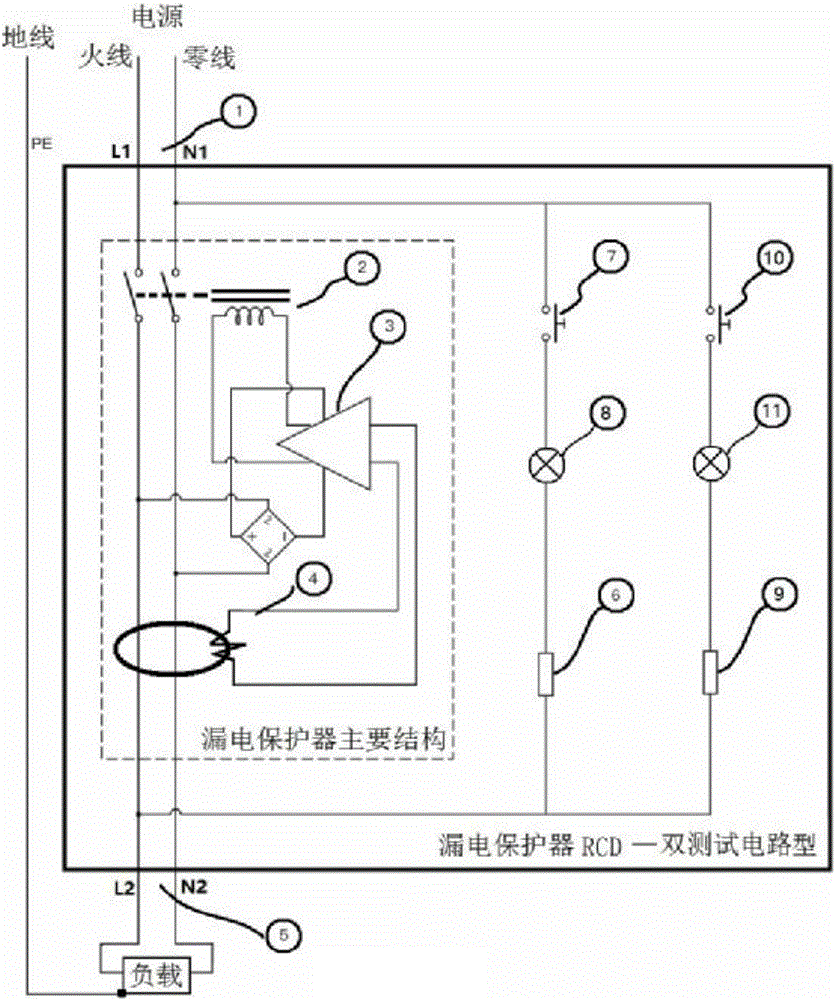
[0055] like Figure 4, as shown in 6, the test circuit can generate two transient simulated leakage currents, the circuit structure includes a bridge rectifier BR1, its two AC input pins are connected to the neutral line N1 of the power input terminal of the leakage protector and the leakage protector The live wire L2 of the power supply output terminal, the negative (-) pin of BR1 is connected to the common return point COM (also known as the common end, common connection point) of the whole circuit, the positive (+) pin of BR1 is connected to the first button SW1 (NO type) and The second button SW2 (NO type) has a common end, the other end of SW1 is connected to the anode of the light emitting diode LED1, and the other end of SW2 is connected to the anode of the light emitting diode LED2. The cathode of LED1 is connected to the common end of the first resisto...


PUM


Abstract

The invention discloses a method and a circuit for testing instantaneous currents of electric leakage protectors. The method is implemented by the circuit which is connected with input and output ends of the electric leakage protectors. The circuit comprises a rectification unit, a test key or two test keys, a current unit and a current chopping unit. A simulation electric leakage current can be generated by the current unit and can be automatically chopped by the current chopping unit. The single simulation electric leakage current can be generated by the current unit when the test keys are pushed, and can be automatically chopped by the current chopping unit after the simulation electric leakage current lasts for the duration ranging from 0.1 second to 0.2 second. The method and the circuit have the advantages that the circuit for testing the instantaneous currents of the electric leakage protectors comprises electronic components with low power, accordingly, the reliability and miniaturization of circuits can be improved, whether the states of the electric leakage protectors are excellent or not can be tested by the circuit, and the tripping response sensitivity of the electric leakage protectors further can be tested by the circuit; the method and the circuit can be applied onto a single test key circuit of a general electric leakage protector and also can be applied to an electric leakage protector with double test key circuits.

Description

technical field [0001] The invention relates to a leakage protector for electric safety equipment, which belongs to the field of low-voltage electric appliances, and in particular to an instantaneous current testing method and a testing circuit of a leakage protector. Background technique [0002] In the traditional power distribution system, leakage protectors are the most effective equipment to prevent personal electric shock accidents, so now it seems that leakage protectors are installed in every place that uses electricity. However, after installation, it does not mean absolute safety or eternal safety. Leakage protectors, like other electrical appliances, are sometimes damaged, or the tripping action with safety protection functions is slow due to aging, so if you do not perform regular functional inspections on it, Once the leakage protector fails, it cannot effectively implement its leakage tripping protection action, and dangerous electric shock accidents are prone ...

Claims


Application Information

Patent Timeline
IPC IPC(8): G01R19/22G01R1/30
CPCG01R1/30G01R19/22
Inventor 许良炎
Owner 许良炎
Why Eureka
Try Eureka