Unlock instant, AI-driven research and patent intelligence for your innovation.

Electromagnetically controlled permanent-magnet magnetic power machine

An electromagnetic control and permanent magnet technology, applied in the direction of generators/motors, electrical components, etc., can solve the problems of low utilization rate of magnetic energy and high power consumption

Active Publication Date: 2017-05-10
周建平
View PDF9 Cites 5 Cited by
  • Summary
  • Abstract
  • Description
  • Claims
  • Application Information

AI Technical Summary

Problems solved by technology

Therefore, in half of the actual operation of the device, a magnetic field obtained by converting electric energy that can overcome the influence of the original permanent magnet magnetic field and form a magnetic repulsion torque is required, which consumes a lot of electric energy and the utilization rate of magnetic energy is not high.
However, in the technical solution of Chinese patent CN104054242A, during the entire operation period, electric energy is applied to the first electromagnet coil or the second electromagnet coil to generate an electromagnetic field that interacts with the magnetic field of the rotor permanent magnet, and there is also a high power consumption. , the problem of low utilization rate of magnetic energy

Method used


Image

  • Electromagnetically controlled permanent-magnet magnetic power machine
  • Electromagnetically controlled permanent-magnet magnetic power machine
  • Electromagnetically controlled permanent-magnet magnetic power machine

Examples


Embodiment Construction

[0026] The present invention will be further described below in conjunction with the examples, but not as a limitation to the present invention.

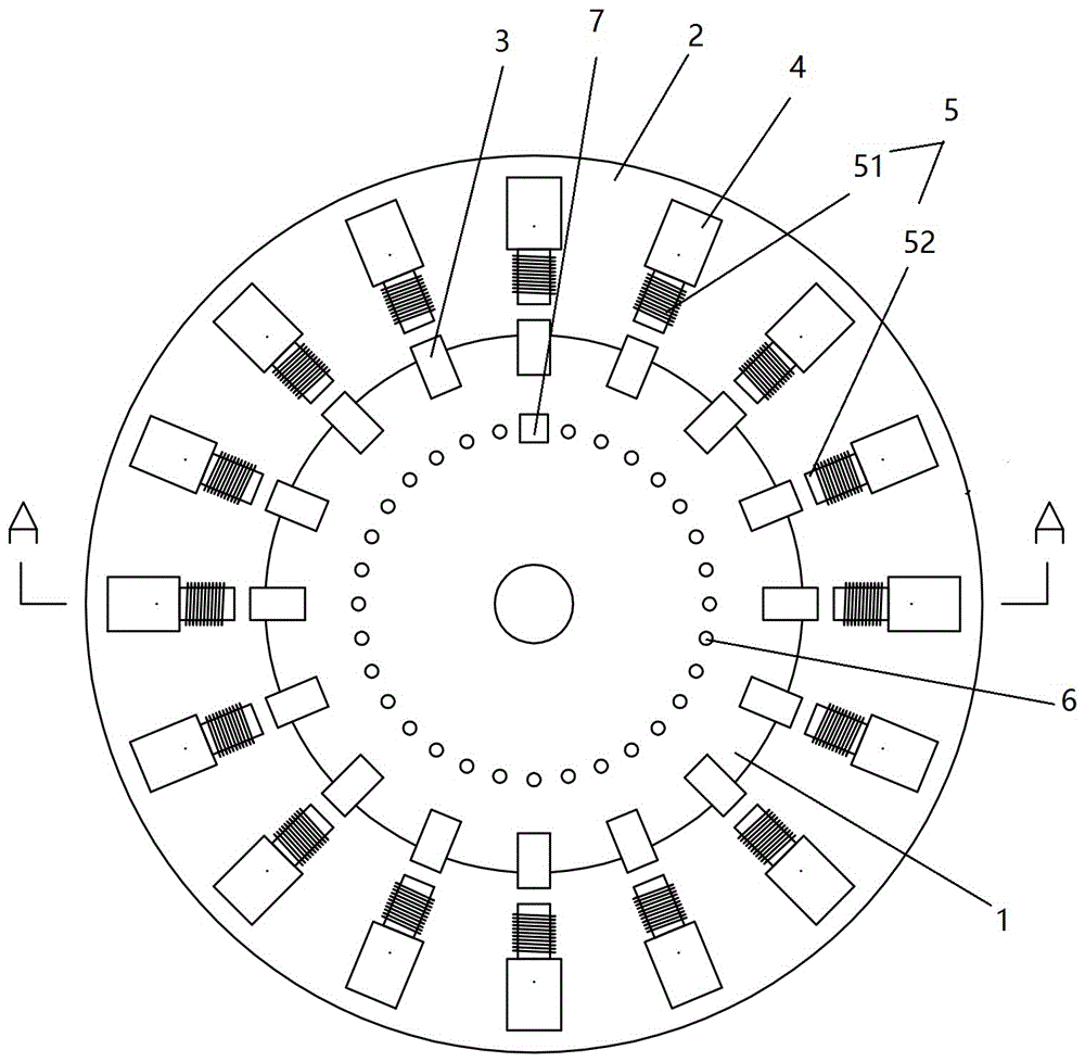
[0027] Such as figure 1 and figure 2 As shown, the electromagnetic control permanent magnet magnetic energy power machine involved in this embodiment includes:

[0028] The rotor 1 and the stator 2 are provided with a plurality of first permanent magnets 3 at equal intervals in the circumferential direction of the rotor 1, and at least one magnetic body is provided in the circumferential direction of the stator 2. figure 1 In the electromagnetic control permanent magnet power machine shown, the number of magnetic bodies provided in the stator 2 is equal to the number of the first permanent magnets 3 of the rotor 1. The magnetic bodies are also arranged at equal intervals, so that the circumferential included angle between two adjacent magnetic bodies is equal to the circumferential included angle between two adjacent first permanent magn...


PUM


Abstract

The invention discloses an electromagnetically controlled permanent-magnet magnetic power machine, which comprises a rotor and a stator. On one of the stator and the rotor, a plurality of first permanent magnets are arranged at equal intervals in the circumferential direction. On the other one of the stator and the rotor, at least one magnetic body is arranged in the circumferential direction. The magnetic body is provided with magnetic poles opposite to the magnetic poles of the first permanent magnets. The magnetic body is composed of second permanent magnets and an electromagnet. The electromagnet is positioned between the first permanent magnets and the second permanent magnets. The electromagnet is provided with an electromagnetic coil and an iron core. The iron core is connected with a magnetic pole at one ends of the second permanent magnets. The magnetic poles of the first permanent magnets and the second permanent magnets, which are opposite to each other, are the same in polarity. At different moments, the electromagnet is electrified in positive and negative directions and the rotor outputs a torque. At the cost of a small amount of electric energy input for the permanent-magnet magnetic power machine, the conversion between the magnetic energy and the mechanical energy is realized based on the magnetic energy of the permanent magnets of the stator and the rotor. Meanwhile, the utilization rate of the magnetic energy is high.

Description

Technical field [0001] The invention relates to a power machine, in particular to an electromagnetic control permanent magnet power machine. Background technique [0002] There is no lack of research on the use of permanent magnets in the existing technology. It is a feasible way to use permanent magnets to drive the rotor to rotate to obtain mechanical energy and then to drive the engine to generate electricity. For the conversion of magnetic energy to mechanical energy, Chinese patent CN2316767Y discloses a high-efficiency permanent magnet power machine, which is evenly distributed on the rotor aluminum disk and the stator aluminum disk, and a plurality of permanent magnets are installed and fixed, and one side of the rotor permanent magnet is equipped with a rotor coil , The power lead of the rotor coil is connected with the intermittent current device, and the intermittent current device is electrically connected to the power supply through the brush. Chinese patent CN104054...

Claims


Application Information

Patent Timeline
IPC IPC(8): H02N11/00
CPCH02N11/006
Inventor 周建平
Owner 周建平
Features
  • R&D
  • Intellectual Property
  • Life Sciences
  • Materials
  • Tech Scout
  • Unparalleled Data Quality
  • Higher Quality Content
  • 60% Fewer Hallucinations
Learn More