

Control system for suppressing torque ripples of brushless direct current motor and torque ripple suppression method for control system
A brushed DC motor and motor controller technology, applied in torque ripple control, control system, electronic commutation motor control, etc. The effect of speed of response
- Summary
- Abstract
- Description
- Claims
- Application Information
AI Technical Summary
Problems solved by technology
Method used
Image

Examples
specific Embodiment approach 1
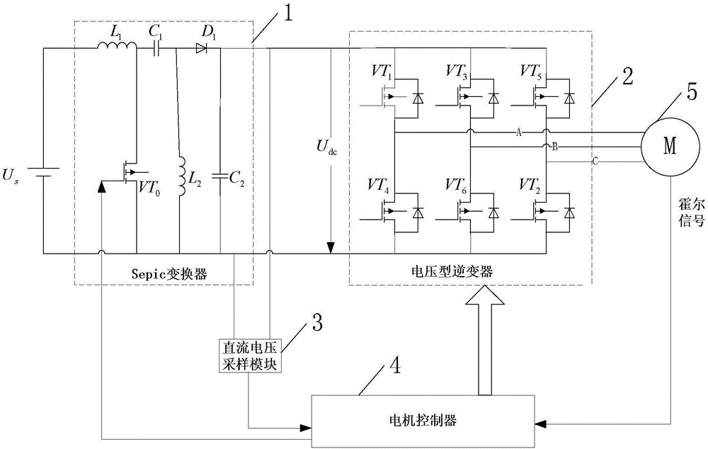
[0050] Specific implementation mode one: see figure 1 Describe this embodiment, a brushless DC motor torque ripple suppression control system described in this embodiment includes a DC power supply U s , Sepic converter 1, voltage type inverter 2, DC voltage sampling module 3 and motor controller 4;
[0051] DC power supply U s The anode of the positive pole is connected to the positive pole input terminal of the Sepic converter 1, and the DC power supply U s The negative pole of is connected to the negative pole input terminal of Sepic converter 1;
[0052] The output end of the Sepic converter 1 is connected to the input end of the voltage type inverter 2, and the output end of the voltage type inverter 2 is connected to the three-phase winding of the controlled brushless DC motor 5;
[0053] The DC voltage sampling module 3 is used to collect the DC voltage output by the Sepic converter 1, and sends the collected DC voltage signal to the motor controller 4;
[0054] Col...
specific Embodiment approach 2
[0056] Specific implementation mode two: see figure 1 Describe this embodiment, the difference between this embodiment and the brushless DC motor torque ripple suppression control system described in the first embodiment is that the Sepic converter 1 includes an inductor L 1 , inductance L 2 , capacitance C 1 , capacitance C 2 , Diode D 1 and MOSFET tube VT 0 ;
[0057] Inductance L 1 One end of the DC power supply U s the positive connection of the
[0058] Inductance L 1 The other end of the capacitor C 1 One end and the MOSFET tube VT 0 the source connection,
[0059] Capacitance C 1 The other end of the inductor L is simultaneously 2 one end of the diode D 1 the anode connection,
[0060] Diode D 1 The cathode and capacitance C 2 One end of the diode D is connected 1 The negative electrode of is used as an output end of Sepic converter 1;
[0061] DC power supply U s The negative pole of the MOSFET tube VT at the same time 0 The drain, inductance L 2 ...
specific Embodiment approach 3
[0062] Specific implementation mode three: see figure 1 Describe this embodiment. The difference between this embodiment and the brushless DC motor torque ripple suppression control system described in Embodiment 1 or 2 is that the voltage-type inverter 2 is a three-phase voltage-type bridge Inverter, three-phase voltage type bridge inverter including 6 switching tubes VT 1 to VT 6 , and 6 switching tubes VT 1 to VT 6 Both are MOSFET tubes,
[0063] Among them, the upper bridge arm of the three-phase voltage type bridge inverter is the switching tube VT 1 , VT 3 , VT 5 , the lower bridge arm is the switching tube VT 4 , VT 6 , VT 2 ;
[0064] A diode is connected in antiparallel between the drain and source of each MOSFET,
[0065] Switch tube VT 1 to VT 6 The gates of each are used to receive the control signal output by the motor controller 4.
PUM
 Abstract
Description
Claims
Application Information