Check patentability & draft patents in minutes with Patsnap Eureka AI!

CMOS clock generator

A technology of clock generator and comparator, which is applied in the direction of pulse generation, electric pulse generation, electrical components, etc., can solve the problem of reducing the accuracy of the clock cycle, and achieve the effect of improving accuracy and reducing temperature coefficient

Inactive Publication Date: 2017-05-10
IPGOAL MICROELECTRONICS (SICHUAN) CO LTD
View PDF4 Cites 0 Cited by
  • Summary
  • Abstract
  • Description
  • Claims
  • Application Information

AI Technical Summary

Problems solved by technology

In the CMOS process, the delay of the comparator will change greatly with the change of temperature (especially in low-power applications), and this change will directly affect the size of the clock cycle, reducing the generated clock cycle. the accuracy of

Method used


Image

  • CMOS clock generator
  • CMOS clock generator
  • CMOS clock generator

Examples


Embodiment Construction

[0027] Embodiments of the present invention will now be described with reference to the drawings, in which like reference numerals represent like elements. As mentioned above, the present invention provides a CMOS clock generator. The clock period of the clock signal produced by the CMOS clock generator of the present invention has nothing to do with the delay of the comparator, which avoids the delay caused by the difference of the comparator under different temperature conditions. The problem of different output clock periods reduces the temperature coefficient and improves the accuracy of the clock period.

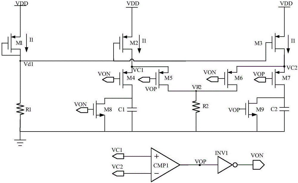
[0028] Please refer to figure 2 , figure 2 It is a structural block diagram of the CMOS clock generator of the present invention. As shown in the figure, the CMOS clock generator of the present invention includes a current generating unit, a periodic signal generating unit, a voltage negative feedback unit and a square wave signal generating unit. The current gener...


PUM


Abstract

The invention discloses a CMOS clock generator comprising a current generation unit, a periodic signal generation unit, a voltage negative feedback unit, and a square wave signal generation unit. The current generation unit connected with an external power supply, the periodic signal generation unit and the voltage negative feedback unit respectively provides working currents for the periodic signal generation unit and the voltage negative feedback unit; the periodic signal generation unit connected with the voltage negative feedback unit and the square wave signal generation unit generates a periodic ramp signal; the square wave signal generation unit connected with the voltage negative feedback unit converts the periodic ramp signal into a square wave signal and outputs a clock signal; and the voltage negative feedback unit is used for adjusting the cycle of the periodic ramp signal generated by the periodic signal generation unit. Because the clock cycle of the clock signal generated by the CMOS clock generator is independent of delay of a comparator, the temperature coefficient can be reduced and the accuracy of the clock cycle can be improved.

Description

technical field [0001] The present invention relates to the field of integrated circuits, more specifically to a CMOS clock generator. Background technique [0002] refer to figure 1 , the CMOS clock generator of prior art is made up of three parts: by MOS tube M1, M2, M3, the electric current generation unit that resistance R1 forms; By MOS tube M4, M5, M6, M7, M8, M9, resistance R2 , a periodic signal generation unit composed of capacitors C1 and C2, wherein the capacitors C1 and C2 are capacitors with identical specifications and parameters, and their capacitance values ​​are both C. A square wave generation unit composed of a comparator CMP1 and an inverter INV1. [0003] Assuming that the current flowing through the MOS transistor M1 is I1 in the CMOS clock generator of the prior art, the current I1 is: [0004] I1=Vd1 / R1 [0005] Wherein, Vd1 is the drain node voltage of the MOS transistor M1. [0006] The MOS transistors M1 , M2 and M3 form a current mirror struc...

Claims


Application Information

Patent Timeline
IPC IPC(8): H03K3/011H03K3/353
CPCH03K3/011H03K3/353
Inventor 何力
Owner IPGOAL MICROELECTRONICS (SICHUAN) CO LTD
Features
  • R&D
  • Intellectual Property
  • Life Sciences
  • Materials
  • Tech Scout
  • Unparalleled Data Quality
  • Higher Quality Content
  • 60% Fewer Hallucinations
Learn More