A centralized power monitoring system and monitoring method thereof

A power monitoring and centralized monitoring technology, which is applied in transmission systems, digital transmission systems, electrical components, etc., can solve the problems of high-efficiency transmission of data or information and large processor loads that are difficult to meet in large-scale CAN bus networks, and achieve firmware library functions The effects of shortening, enhancing management, and flexible data transmission

Active Publication Date: 2020-08-07
EAST CHINA UNIV OF SCI & TECH
View PDF2 Cites 0 Cited by
  • Summary
  • Abstract
  • Description
  • Claims
  • Application Information

AI Technical Summary

Problems solved by technology

In the process of processing data or information transmission, when implementing CAN bus data or information transfer with different baud rates, the processor load is relatively large, and it is difficult to meet the efficient transmission of data or information in large CAN bus networks

Method used


Image

  • A centralized power monitoring system and monitoring method thereof
  • A centralized power monitoring system and monitoring method thereof
  • A centralized power monitoring system and monitoring method thereof

Examples


Embodiment 1

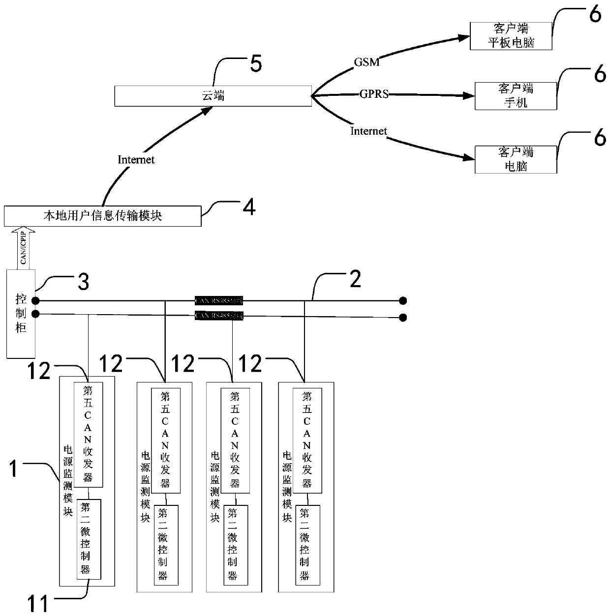
[0061] Such as figure 1 As shown, a centralized power monitoring system includes multiple power monitoring modules 1 , multiple CAN / RS485 buses 2 , a control cabinet 3 , a local user information transmission module 4 , a cloud 5 and at least one client 6 .

[0062] Each power monitoring module 1 is used for power data or information of its corresponding electrical equipment. Wherein, each power monitoring module 1 includes a second microcontroller 11 and a fifth transceiver. Wherein, the second microcontroller is used for processing the monitored power data or information; and setting the value of the sending data filtering register of the power monitoring module 1 . The fifth transceivers are all connected to the second microcontroller 11 , and the second microcontroller 11 packs the collected power data or information and forwards them to the CAN / RS485 bus 2 through the fifth transceivers.

[0063] Wherein, the fifth transceiver includes a fifth CAN transceiver 12 and / or a...

Embodiment 2

[0093] The difference between this embodiment and Embodiment 1 is that the centralized power monitoring system also includes at least one repeater 7, and each repeater 7 is connected between the CAN / RS485 bus 2 of the upper and lower levels. , the repeater 7 is used to forward the power data or information from the CAN / RS485 bus 2 at the lower level to the CAN / RS485 bus 2 at the upper level.

[0094]This embodiment is applicable to the transmission of power supply data or information over a longer distance. In this embodiment, taking the CAN bus as an example, the CAN bus at the lowest level is connected to each power monitoring module 1, and then the CAN bus at the lowest level passes through a The repeater 7 is connected to the CAN bus of the upper level, so that the layers are classified, and finally connected to the control cabinet 3 through a CAN bus. Alternatively, the power monitoring modules 1 are connected to the above-mentioned CAN buses at all levels, and the power ...


PUM


Abstract

The invention discloses a power supply centralized monitoring system which comprises a plurality of power supply monitoring modules and a plurality of paths of CAN / RS485 buses, wherein each power supply monitoring module is used for monitoring corresponding power supply data or information; each power supply monitoring module is connected to the corresponding CAN / RS485 bus; each CAN / RS485 bus is connected to a control cabinet; the CAN / RS485 buses are used for transmitting the power supply data or information monitored by the power supply monitoring modules to the control cabinet; the control cabinet parses the received power supply data or information, displays the power supply data or information on a touch screen of the control cabinet and simultaneously, uploads the power supply data or information to a local user information transmission module; and by the local user information transmission module, the power supply data or information is transmitted to a cloud end. The invention further discloses a monitoring method of the power supply centralized monitoring system.

Description

technical field [0001] The invention relates to the fields of communication, fire protection and the like, in particular to a centralized power supply monitoring system and a monitoring method thereof. Background technique [0002] In the fire protection system of large buildings, there are a large number of live equipment such as fire elevators, fire hydrants, emergency lighting, and fire shutters, which need to be monitored online for their voltage, current, and power indicators to ensure their stable and safe operation. [0003] In the fire monitoring system, power supply power is one of the main monitoring indicators. In a building, there are often thousands or even hundreds of detection nodes, so if we want to centrally monitor the data of each node, we need a field bus that supports distributed control and real-time control, and connects the nodes together. , for data collection and transmission. The CAN bus just fits this need. [0004] CAN bus is a multi-master se...

Claims


Application Information

Patent Timeline
Patent Type & Authority Patents(China)
IPC IPC(8): H04L29/08H04L12/40
CPCH04L12/40006H04L67/025H04L67/12H04L67/125H04L2012/40215
Inventor 易建军李宜李叶翔张恒段鹏洋胡家豪崔晓惠
Owner EAST CHINA UNIV OF SCI & TECH
Why Eureka
Try Eureka