

Piston ring
A piston ring and curved surface technology, applied in the field of pressure rings, can solve the problem of not taking the piston or piston ring abrasion countermeasures or edge load countermeasures, and achieve the effect of avoiding major damage, avoiding abrasion, and excellent wear resistance.
- Summary
- Abstract
- Description
- Claims
- Application Information
AI Technical Summary
Problems solved by technology
Method used
Image

Examples
Embodiment 1
[0043] Embodiment 1 (first piston ring)
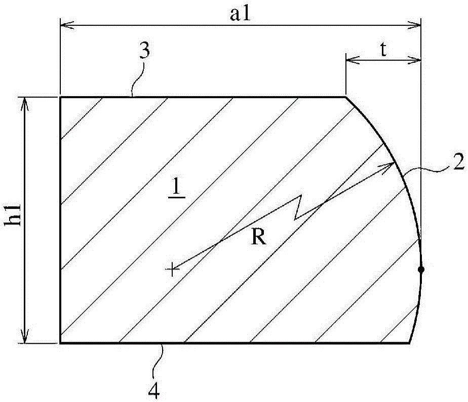
[0044] Composed of materials Containing C: 0.48%, Si: 0.21%, Mn: 0.79%, Cr: 1.02%, V: 0.22% in mass %, bar steel with an outer diameter of 110mm and a length of 200mm, rolled by rings Processing is used to manufacture cylindrical raw materials, and mechanical processing is performed to produce a steel top ring with a rectangular cross-section with a nominal diameter (d1) of 330 mm, a width (h1) of 5 mm, and a thickness (a1) of 9 mm. Next, by gas nitriding at 460°C for 5 hours, a nitride layer of about 70 μm is formed on the entire surface of the ring, and a cermet spray protection film of about 500 μm is formed on the outer periphery. Composite material particles in which fine Cr carbide particles are dispersed in a Ni alloy substrate by flame spraying are the main constituent particles (SM5241 powder from Sulzer Metco Co., Ltd.), and finishing grinding to spraying is finally performed. The film thickness of the protective film was ab...
Embodiment 2
[0052] Embodiment 2 (second piston ring)
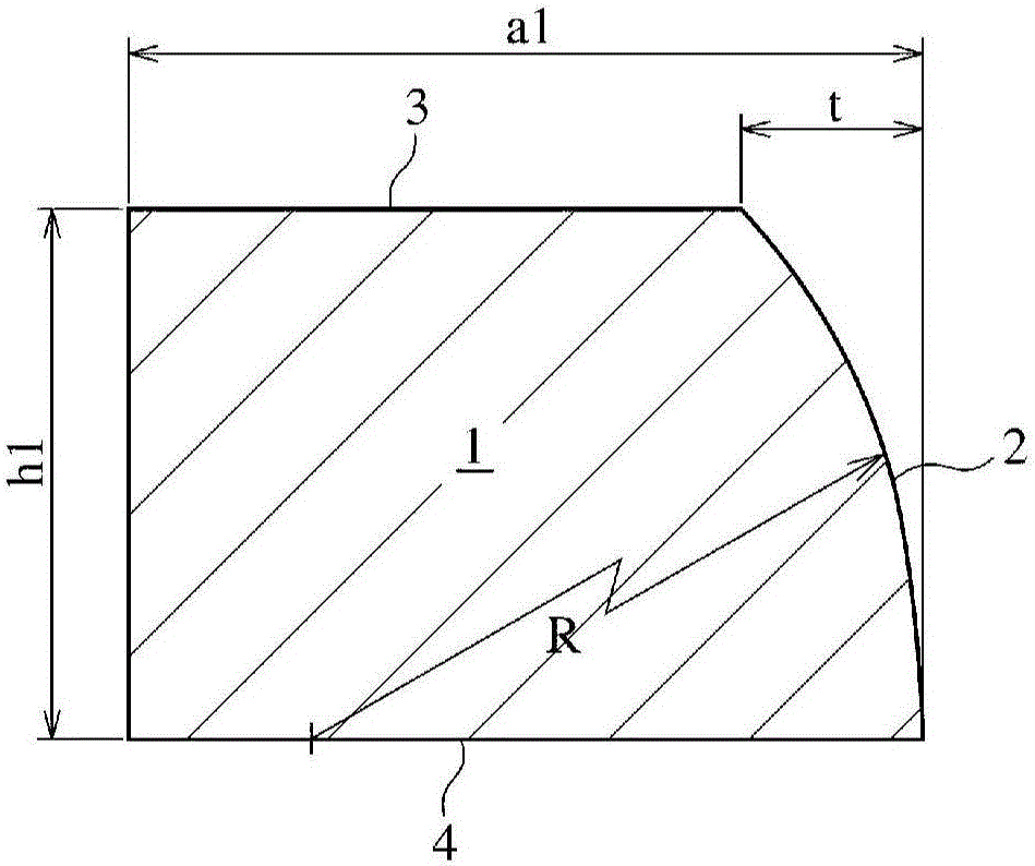
[0053] In addition to setting the parameters of the deformed involute curve as a=6000, b=3, α=1, β=1.5, and inverting the first curved surface so that the radius of curvature decreases from the crank chamber side to the combustion chamber side A steel top ring was produced in the same manner as in Example 1 except for formation. In this case, the radius of curvature at a position 0.5 mm from the lower side is 340 mm, the radius of curvature at the top is 270 mm, and the radius of curvature at a position 0.5 mm from the upper side is 100 mm. The retreat amount (t) of the outer peripheral sliding surface on the combustion chamber side was 0.016 mm, which was 0.0048% of the nominal diameter (d1). In addition, the same actual machine test as in Example 1 was carried out, and as a result, there was no failure in any of the cylinders, and there was no abnormality in the sliding surface of the top ring.
Embodiment 3-5
[0054] Embodiment 3-5 (first piston ring)
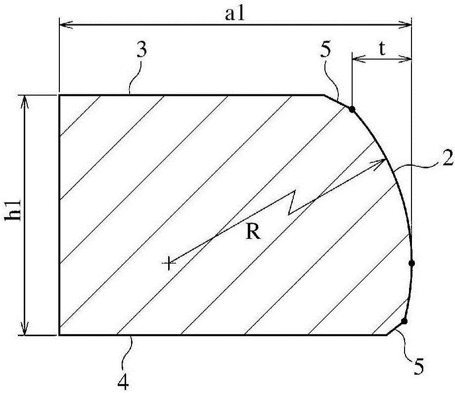
[0055] Steel top rings of Examples 3 to 5 were manufactured in the same manner as in Example 1 except that parameters a, b, α, and β of the deformation involute curve were set to the values shown in Table 1. Regarding the radius of curvature at the lower side (0.5 mm from the lower side), the apex position, and the upper side (0.5 mm from the upper side), the radius of curvature and the amount of retreat (t) in Examples 3 to 5 are also the same as The results of Examples 1 and 2 are shown in Table 1 together. In addition, when the top rings of Examples 3 to 5 were attached to two cylinders each, a real machine test was carried out in the same manner as in Example 1. As a result, all the cylinders using the top rings had no failure, and the slipping of the top rings There is no abnormality in the face.
[0056] [Table 1]
[0057]
[0058] *The amount of retraction refers to the amount of retraction (t) of the outer peripheral ...
PUM
 Abstract
Description
Claims
Application Information