
High-resolution scanning microscopy with discrimination between at least two wavelength ranges

A scanning microscopy, high-resolution technology, used in microscopy, material analysis, material analysis by optical means, etc., can solve problems such as cost and expensive flat detectors

Inactive Publication Date: 2017-05-10
CARL ZEISS MICROSCOPY LLC
View PDF14 Cites 7 Cited by
  • Summary
  • Abstract
  • Description
  • Claims
  • Application Information

AI Technical Summary

Problems solved by technology

In conventional laser scanning microscopy (which uses a non-position-resolving detector behind a confocal well plate (so-called pinhole)), this requirement is basically not problematic, when applying the process according to EP2317362A1 In the sampled planar detector, the cost is obviously incurred, and at this time, such a planar detector is expensive

Method used


Image

  • High-resolution scanning microscopy with discrimination between at least two wavelength ranges
  • High-resolution scanning microscopy with discrimination between at least two wavelength ranges
  • High-resolution scanning microscopy with discrimination between at least two wavelength ranges

Examples


Embodiment Construction

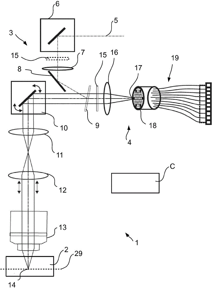
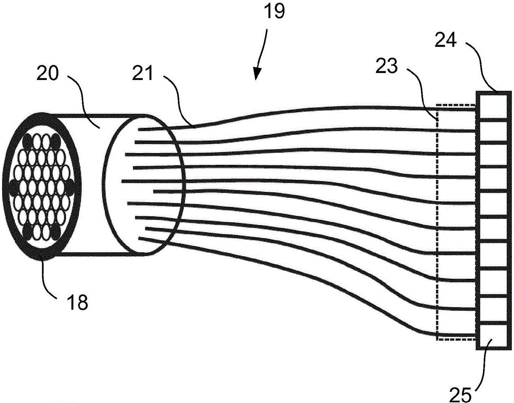
[0038] figure 1 A laser scanning microscope 1 is schematically shown, which is designed for microscopic imaging of a sample 2 . A laser scanning microscope (abbreviated as LSM hereinafter) is controlled by a control device C, and includes an illumination optical path 3 and an imaging optical path 4 . The illumination light path illuminates a point in the test 2, and the imaging light path 4 images the point in a diffraction-limited manner for detection. The illumination optical path 3 and the imaging optical path 4 share an optical device.

[0039] Illumination of the sample 2 takes place in the LSM 1 by means of a provided laser beam 5 which is coupled into a mirror 8 by means of a deflection mirror 6 and a lens 7 which are not further functionally required. The mirror 8 is responsible for transmitting the laser beam 5 at a reflection angle to an incoupling element, for example an emission filter 9 . For an overview of the representation, only the main axis of the laser be...


PUM


Abstract

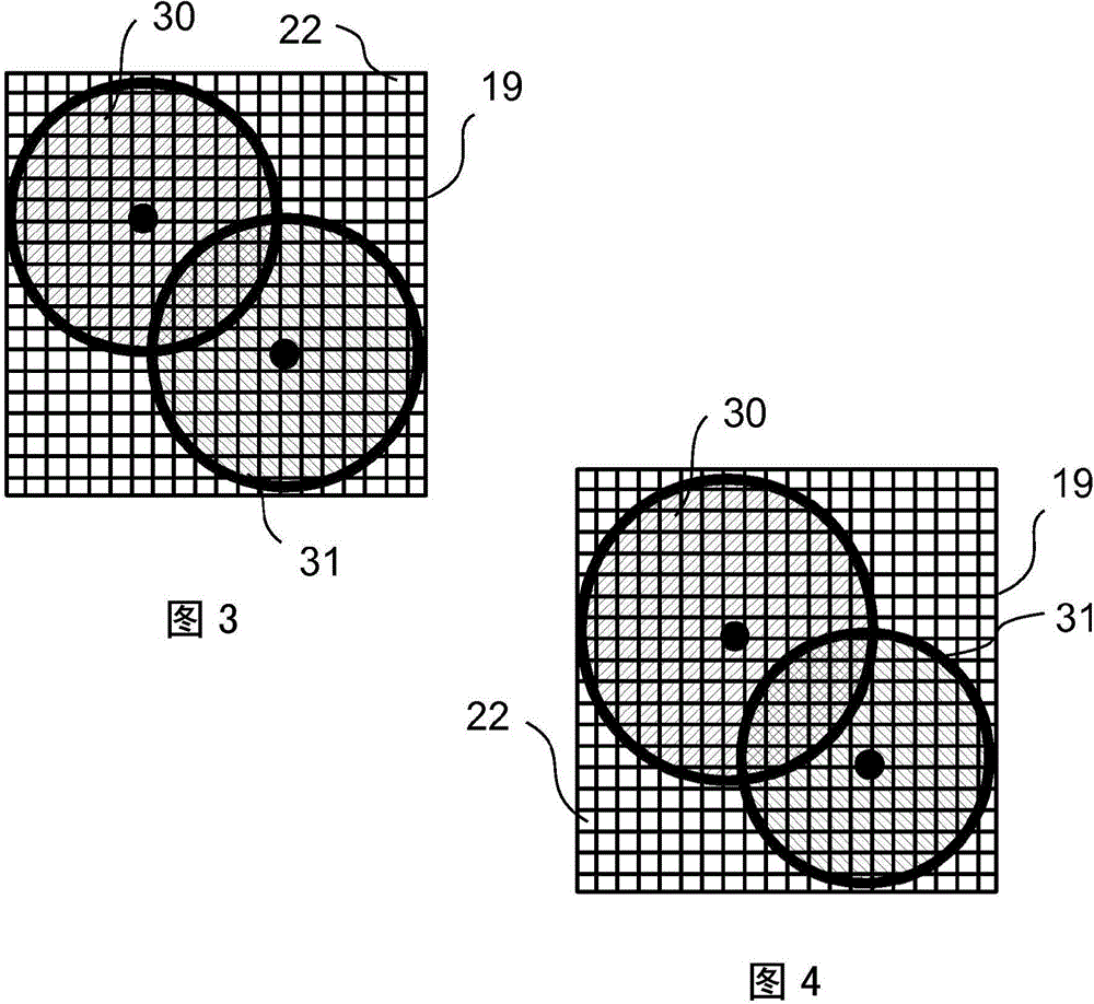
For the purposes of high-resolution scanning microscopy, a sample (2) is excited by illumination radiation (5) to emit fluorescence radiation in such a way that the illumination radiation (5) is focused at a point in or on the sample (2) to form a diffraction-limited illumination spot (14). The point is imaged in a diffraction image (17) on a spatially resolving two-dimensional detector (19) in a diffraction-limited fashion, wherein the two-dimensional detector (19) has a spatial resolution which resolves a diffraction structure of the diffraction image (17). The sample (2) is scanned by means of various scanning positions with an increment that is smaller than half the diameter of the illumination spot (14). An image of the sample (2) with a resolution that is increased beyond a resolution limit of the image is generated from the data of the two-dimensional detector (19) and from the scanning positions assigned to these data. For the purposes of discriminating between at least two predetermined wavelength ranges in the fluorescence radiation of the sample (2), a number of Airy disks (30-33) corresponding to the at least two predetermined wavelength ranges are generated on the two-dimensional detector (19), which Airy disks are offset laterally from one another such that the diffraction image (17) consists of the mutually offset Airy disks (30-33). The Airy disks (30-33) are evaluated when generating the image of the sample (2).

Description

technical field [0001] The invention relates to a method for high-resolution scanning microscopic imaging of a sample, wherein the sample is stimulated to emit fluorescent radiation by means of illumination radiation in such a way that the illumination radiation is focused into or on the sample at one point to form a diffraction-limited spot that is imaged into a diffraction pattern on a planar detector with position-resolving capability, wherein the planar detector has position-resolving capability for the diffraction pattern The diffraction structure is resolved, the point is shifted to different scanning positions relative to the sample with a step width less than half the spot diameter, and the planar detector is read, based on the data of the planar scanner and based on the data corresponding to the above-mentioned The scanning position produces an image of the sample with increased resolution beyond the resolution limit of the imaging. [0002] The invention also relate...

Claims


Application Information

Patent Timeline
Patent Type & Authority Applications(China)
IPC IPC(8): G02B21/00G02B27/58
CPCG02B21/0032G02B21/0076G02B21/008G02B27/58G01N21/6458G02B21/0072
Inventor 因格·克莱珀拉尔夫·耐茨姚赫尼·诺维考
Owner CARL ZEISS MICROSCOPY LLC
Learn More