Method For Manufacturing Reflective Optical Element, Reflective Optical Elements, Euv-Lithography Apparatus And Methods For Operating Optical Elements And Euv-Lithography Apparatus, Methods For Determining The Phase Shift, Methods For Determining The Layer Thickness, And Apparatuses For Carrying Out The Methods

a technology of reflective optical elements and euv lithography, which is applied in the field of manufacturing reflective optical elements, reflective optical elements, euv lithography apparatus and methods, and methods for determining layer thickness, etc., can solve the problems of contaminated reflective optical elements, damage to the surface of reflective optical elements, and impaired reflection and the lifetime of such reflective optical elements

Inactive Publication Date: 2007-12-13
CARL ZEISS SMT GMBH
View PDF7 Cites 41 Cited by
  • Summary
  • Abstract
  • Description
  • Claims
  • Application Information

AI Technical Summary

Benefits of technology

[0058] Two or more samples are advantageously introduced into the apparatus for measurement, and they are electrically connected to one another in series.
[0059] The invention is further realized in a reflective optical element for the extreme ultraviolet up to the soft x-ray wavelength range comprising a multilayer system with cap layer system with at least one layer consisting of a transition metal or an alloy, compound or mixture containing a transition metal, being optimized for an operating wavelength in the extreme ultraviolet up to the soft x-ray wavelength range which is characterized in that at least one layer- or cap layer-thickness is chosen in such a way that during irradiation at the operating wavelength a standing electromagnetic wave is formed in such a way that it forms an intensity maximum in the area of the free interfa

Problems solved by technology

The reflectance and the lifetime of such reflective optical elements are particularly impaired by contamination of the surface during irradiation at the operating wavelength through deposition of carbon and oxidation of the surface.
The reflective optical elements are contaminated by residual gases from the vacuum atmosphere during operation.
As e.g. EUV-lithography apparatuses do not allow the necessary throughput with a loss of reflectance of 1% per reflective optical element, the contamination layer has to be removed in a cleaning process which may last up to 5 hours.
Furthermore, such a cleaning process involves the risk that the surface of the reflective optical element is damaged

Method used


Image

  • Method For Manufacturing Reflective Optical Element, Reflective Optical Elements, Euv-Lithography Apparatus And Methods For Operating Optical Elements And Euv-Lithography Apparatus, Methods For Determining The Phase Shift, Methods For Determining The Layer Thickness, And Apparatuses For Carrying Out The Methods
  • Method For Manufacturing Reflective Optical Element, Reflective Optical Elements, Euv-Lithography Apparatus And Methods For Operating Optical Elements And Euv-Lithography Apparatus, Methods For Determining The Phase Shift, Methods For Determining The Layer Thickness, And Apparatuses For Carrying Out The Methods
  • Method For Manufacturing Reflective Optical Element, Reflective Optical Elements, Euv-Lithography Apparatus And Methods For Operating Optical Elements And Euv-Lithography Apparatus, Methods For Determining The Phase Shift, Methods For Determining The Layer Thickness, And Apparatuses For Carrying Out The Methods

Examples


Embodiment Construction

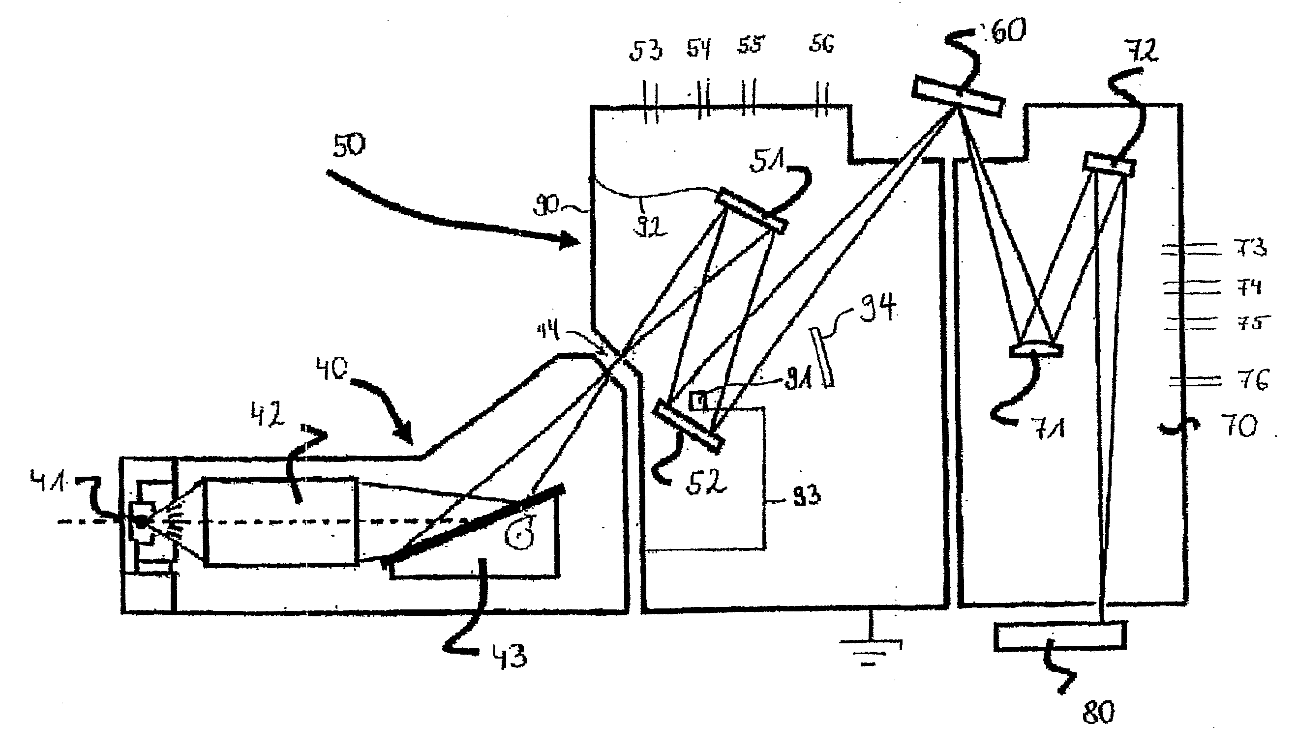
[0080] The manufacturing methods for multilayer systems with a cap layer system known so far suffer from that the determination of the thickness of different layers and cap layers, respectively, can be carried through only in a very imprecise way. In particular, only mean layer thicknesses over the depth of the entire multilayer system can be determined by reflectance measurements. However, this information is sufficient for optimization of the coating process of multilayer systems without cap layer system, as far as optimum reflectance is concerned. This problem is more serious in the production of multilayer systems with a cap layer system. The cap layer system breaks the periodicity such that no reliable information about layer thicknesses can be achieved by mere reflectance measurements. Sticking to the desired multilayer system as precisely as possible is extremely important for cap layer systems in terms of durability properties, in particular contamination resistance, while k...


PUM


Abstract

The invention relates to a method for manufacturing of a multilayer system (25) with a cap layer system (30), in particular for a reflective optical element for the extreme ultraviolet up to the soft x-ray wavelength range, comprising the steps of: 1. preparing a coating design for the multilayer system (25) with cap layer system (30); 2. coating a substrate (20) with the multilayer system (25) with cap layer system (30); 3. spatially resolved measurement of the coated substrate in terms of reflectance and photoelectron current in at least one surface point; 4. comparison of the measured data with data modelled for different thicknesses of the layers (31, 32, 33) of the cap layer system (30) and/or the layers (21, 22, 23, 24) of the multilayer system (25) for determining of the thickness distribution obtained by the coating; 5. if necessary, adjusting of the coating parameters and repeating steps 2 to 5 until the coated thickness distribution coincides with the design. The invention also relates to further manufacturing methods, reflective optical elements, EUV-lithography apparatuses, and methods for operating optical elements and EUV-lithography apparatuses as well as methods for determining the phase shift, methods for determining the layer thickness, and apparatuses for carrying out the methods.

Description

TECHNICAL FIELD OF THE INVENTION [0001] The invention relates to a method for qualifying a reflective optical element and a method for determining a thickness profile of a multilayer system and / or a cap layer system of an optical element for reflecting radiation. [0002] Furthermore, the invention relates to a method for manufacturing multilayer systems with a cap layer system, in particular reflective optical elements for the extreme ultraviolet up to the soft x-ray wavelength range, a corresponding reflective optical element for the extreme ultraviolet up to the soft x-ray wavelength range as well as an EUV-lithography apparatus with at least one such reflective optical element. [0003] Furthermore, the invention relates to a method for manufacturing a reflective optical element for the extreme ultraviolet up to the soft x-ray wavelength range with a cap layer system of constant thickness as well as an EUV-lithography apparatus with at least one such reflective optical element. [000...

Claims


Application Information

Patent Timeline
IPC IPC(8): G03B27/54G01B9/00
CPCG03F7/70958G01B11/0625
Inventor WEDOWSKI, MARCOSHARILOO, NADYEHSCHOLZE, FRANKTUEMMLER, JOHANNES
Owner CARL ZEISS SMT GMBH
Why Eureka
Try Eureka