Method and Arrangement for Collimated Microscopic Imaging

a microscopic imaging and collimation technology, applied in the field of collimation microscopic imaging methods and arrangements, can solve the problems of cumbersome technical aspects of confocal detection in multi-spot arrangement of this kind, and achieve the effect of simple technical implementation

Inactive Publication Date: 2009-10-08
CARL ZEISS MIKROLMAGING
View PDF3 Cites 42 Cited by
  • Summary
  • Abstract
  • Description
  • Claims
  • Application Information

AI Technical Summary

Benefits of technology

[0010]A method and an arrangement in which a high-resolution image is achieved directly (without image processing) with parallel data acquisition is described in the following. The extrafocal background can be eliminated by variable confocal detection. This method and arrangement prevent the above-mentioned disadvantages of the multi-spot arrangement according to the prior art. In particular, an optimal parallelization (maximum density of the simultaneously excited regions of the sample) and a relatively simple technical implementation are made possible by the invention.

Problems solved by technology

A decisive disadvantage of this arrangement is the sequential data acquisition.
This means that a relatively large area around the individual spot interacts with this light distribution, which only allows a low density of the spot and, therefore, meager parallelization.
Further, a confocal detection in a multi-spot arrangement of this kind is cumbersome in technical respects.

Method used


Image

  • Method and Arrangement for Collimated Microscopic Imaging
  • Method and Arrangement for Collimated Microscopic Imaging
  • Method and Arrangement for Collimated Microscopic Imaging

Examples


example

Switching of the Dronpa Protein

[0067]A suitable candidate for switching is the Dronpa protein (Habuchi et al., PNAS 102 (2005) 9511-9516). In this case, the switching off and the excitation are carried out with a wavelength in the range of about 450 nm to 520 nm. Switching on can be carried out in the range of 350 nm to 420 nm. This makes it possible to work, e.g., with the lines of the argon laser at 477 nm and 488 nm and to use a laser diode at 405 nm for switching on. The mutual switching on and off is shown in FIG. 11a). A detailed view of switching off is represented in FIG. 11b). This illustrates the long exposure times of about 5 ms for achieving a sufficient switching off. While the exposure time can be shortened by increasing the intensity, this would reduce the number of possible switching cycles compared to FIG. 11a) in which about 100 switching cycles are shown.

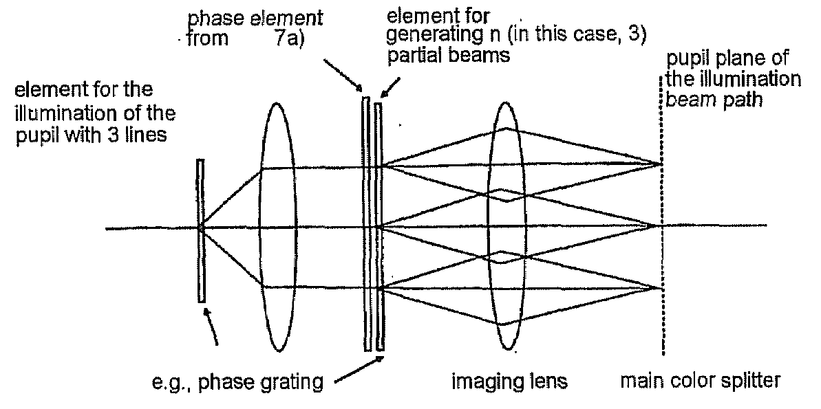
[0068]FIG. 12 shows a schematic view of a preferred illumination unit for a laser scanning microscope for use w...


PUM

PropertyMeasurementUnit
edge lengthaaaaaaaaaa
distanceaaaaaaaaaa
microscopic imagingaaaaaaaaaa

Abstract

A method and arrangement for collimated microscopic imaging, including a first illumination of a sample in at least one region for exciting fluorescence, and a spatially resolving detection of the sample light by detector elements, the detection being associated with the region, wherein by means of a second illumination a sub-division of the region into separate fluorescent partial regions occurs, which are associated with the detector elements. The separation of the partial regions is carried out by the spatial separation of the fluorescent regions by means of intermediate regions having reduced fluorescence or no fluorescence, and/or by means of different spectral properties of the fluorescence from the partial regions.

Description

RELATED APPLICATIONS[0001]The present application is a U.S. National Stage application of International PCT Application No. PCT / EP2007 / 008556 filed on Oct. 2, 2007, which claims benefit of German Application No. DE 10 2006 047 912.2 filed on Oct. 6, 2006, the contents of each are incorporated by reference in their entirety.FIELD OF THE INVENTION[0002]The present invention relates to methods and arrangements for microscopic imaging with structured illumination. Increased spatial resolution is achieved by means of nonlinear interactions between samples, which is known from the prior art. By means of the method and the corresponding arrangements of this invention, this sample interaction is made use of for imaging in such a way that confocal imaging is possible with a resolution that goes beyond the diffraction boundary in all spatial directions with parallel data acquisition.PRIOR ART[0003]The prior art discloses various nonlinear sample interactions which can lead to enhanced spatial...

Claims


Application Information

Patent Timeline
Patent Type & Authority Applications(United States)
IPC IPC(8): G01N21/64
CPCG01N21/6458G02B21/0032G02B21/16G02B21/0076G02B21/0072
Inventor KEMPE, MICHAELKRAMPERT, GERHARDWALD, MATTHIASWOLLESCHENSKY, RALF
Owner CARL ZEISS MIKROLMAGING
Why Eureka
Try Eureka