
Planetary speed reduction type eccentricity-adjustable helical hole-milling device

A planetary deceleration and helical hole milling technology, applied in feeding devices, milling machine equipment, details of milling machine equipment, etc., can solve the problems of large frictional resistance, large adjustment force, low transmission efficiency, etc., and achieve low frictional resistance and low input power. Effect

Active Publication Date: 2017-05-17
DALIAN JIAOTONG UNIVERSITY
View PDF18 Cites 17 Cited by
  • Summary
  • Abstract
  • Description
  • Claims
  • Application Information

AI Technical Summary

Problems solved by technology

[0004] The radial offset structures shown in patent CN200910306026.8, patent CN201020263681.8, patent CN200920308766 and patent CN201310604032.8 all use the inner and outer eccentric sleeve structure to adjust the eccentricity, and the relative rotation angle of the inner and outer sleeves is adjusted online by driving the motor. Change the eccentricity of the tool, but because there is no displacement feedback element, there are a series of problems such as complex online adjustment control algorithm, poor online adjustment reliability, high requirements for the control system, and poor adjustment accuracy; in patent CN201110038893.5, patent CN201110088154. 7. The radial offset structures shown in the patent US6382890B1 and the patent CN201310105521.9 both adopt a double eccentric structure to adjust the eccentricity through the worm gear and worm, but because the worm gear adjusts the eccentricity through a small amount of rotation with a large transmission ratio, not only its transmission efficiency is low, Moreover, the calculation is complicated for nonlinear adjustment, and there is a backlash in the worm gear, which in turn affects the adjustment accuracy; in patent CN201210150627.6 and patent CN201220218351.6, a double wedge structure is adopted, and the linear micro-adjustment is driven by a stepping motor, which greatly affects the control system. The requirements are relatively high; in the patent CN201020148675.8, the radial offset structure adopts a dovetail groove and an offset slider structure, and the rack embedded in the offset slider is driven by a rotating gear to adjust the eccentricity, and the set screw holds the eccentric structure tightly. In the patent CN201210157184.3, the dovetail slider structure is adopted, the eccentricity is adjusted by the spring return structure and the differential screw, the eccentricity is fastened by the wedge locking structure, and the eccentricity is adjusted by the offset slider structure in the patent CN201410334409.7 The backlash is reduced by rotating the movable anti-backlash nut, and the eccentricity is tightened by rotating the tightening screw. Patent CN201020148675.8, patent CN201210157184.3 and patent CN201410334409.7 all adopt direct adjustment, which cannot realize linear micro-adjustment of large transmission ratio; None of the above patents have displacement feedback components to achieve precise eccentricity adjustment
[0005] In the patent CN201210196101.1, the patent CN201310604032.8 and the patent CN201320822144.6, the double eccentric sleeve structure is adopted. When the power of the self-rotating power source is the same and the volume is the same, the space occupied by the inner and outer rotatable sleeves is relatively large; in the patent CN201210150627. In 6, the double wedge structure is adopted, and the ratio of the volume of the double wedge to the volume of the self-rotation power source is large; in the patent CN201210157184.3, the dovetail slider structure is adopted, and the eccentricity is adjusted through the spring return structure and the differential screw. Locking structure tightens the eccentricity. Although the volume of the eccentric structure is smaller than that of the power source, the eccentricity of the overall rotation mechanism is adjusted by the differential screw through the structural surface contact of the dovetail slider. The frictional resistance is large and the adjustment force is large. ; In the patent CN201410334409.7, the offset slider is adopted, and the electric spindle is fixed in the offset slider. Since the offset slider is an outer square and an inner circle, it occupies a large space volume, resulting in the difference between the volume of its adjustment structure and the volume of the rotation power source. bigger
[0006] In the patent CN200910306026.8 and the patent CN201020263681.8, the double eccentric structure is adopted. When the adjustment of the eccentric amount is completed, the position of the double eccentric structure is fixed by the electromagnetic brake, which has high requirements on the control system; in the patent CN201310604032.8, the Double eccentric sleeve structure, the eccentric distance is adjusted online through the dual motor drive inner and outer sleeves, which has high requirements for the control system; in the patent CN201110038893.5, the double eccentric structure, the worm gear and worm adjusts the eccentric distance, and the eccentricity is fixed by the worm gear and worm self-locking, It is prone to failure during the vibration process; in the patent CN201210157184.3, the dovetail groove slider structure is adopted, the eccentricity is adjusted through the spring return structure and the differential screw, and the eccentricity is fastened by the wedge locking structure. In the patent CN201410334409.7 The offset slider structure is used to adjust the eccentricity, and the eccentricity is tightened by rotating the tightening screw. The above patents require a large pre-tightening force due to the small contact area between the screw and the slider, and must be adjusted with the help of a booster tool, which makes the adjustment complicated.

Method used


Image

  • Planetary speed reduction type eccentricity-adjustable helical hole-milling device
  • Planetary speed reduction type eccentricity-adjustable helical hole-milling device
  • Planetary speed reduction type eccentricity-adjustable helical hole-milling device

Examples


Embodiment Construction

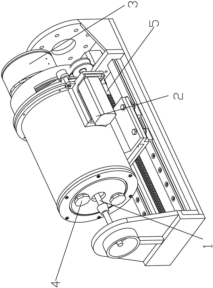
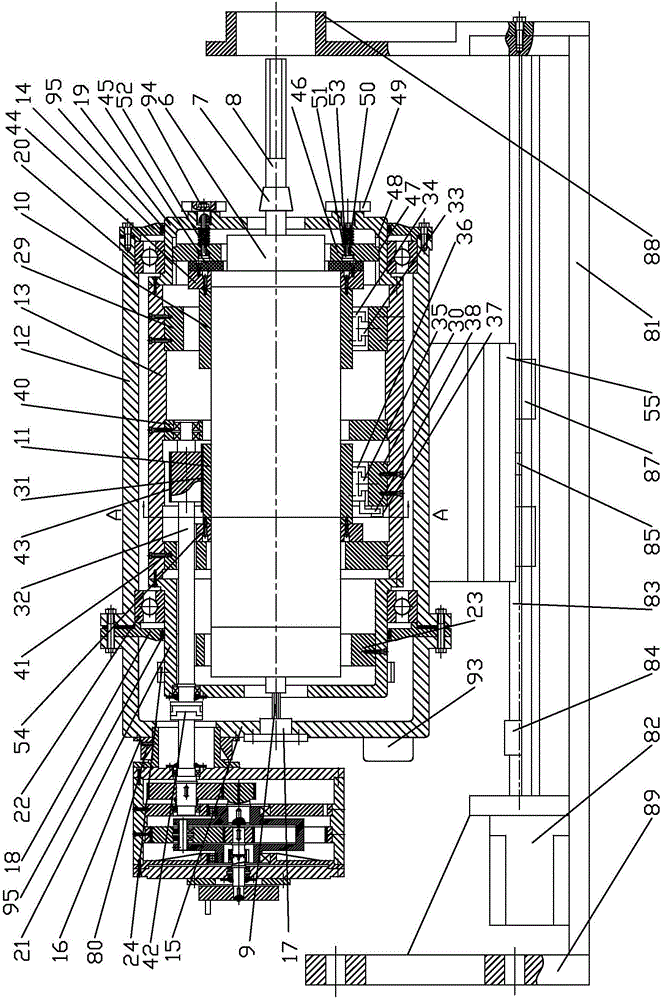
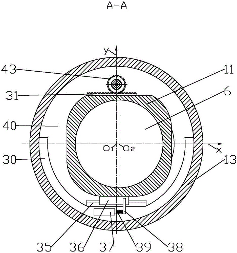
[0044] Such as Figure 1-Figure 7 As shown in the figure, a planetary deceleration type adjusting eccentricity helical milling device includes a rotation system 1, a revolution system 2, a radial eccentricity adjustment system 3, a clamping brake system component 4 and an axial feed system 5;

[0045] The autorotation system 1 includes an electric spindle 6, the front end of the electric spindle 6 is connected to the milling tool 8 through a spring ferrule 7, the rear end of the electric spindle 6 is provided with a wiring 9, and the outer wall of the front section of the electric spindle 6 Electric spindle fixing seat I10 is socketed, and the outer wall of the middle section of the electric spindle 6 is socketed with electric spindle fixing seat II11;

[0046]The revolution system 2 includes a housing sleeve 12 and a revolution sleeve 13, the front end of the housing sleeve 12 is provided with a bearing front end cover 14, and the rear end of the housing sleeve 12 is provided...


PUM


Abstract

The invention discloses a planetary speed reduction type eccentricity-adjustable helical hole-milling device. The planetary speed reduction type eccentricity-adjustable helical hole-milling device is characterized by comprising a rotation system, a revolution system, a radial eccentricity adjusting system, a clamping braking system assembly and an axial feeding system. The radial eccentricity adjusting system can achieve precise trace linear eccentricity adjustment with high transmission ratio, and required input power is small. Compared with sliding block adjusting structures disclosed by existing patents, the radial eccentricity adjusting system can perform adjustment conveniently with less labor, and compared with a dual eccentric sleeve structure and an offset sliding block structure, the ratio of the size of the adjusting structure to the size of a rotation power source is greatly decreased, the occupied space is reduced, and the dead weight is reduced relatively in case of the identical material. Compared with an electromagnetic brake, the clamping braking system assembly can perform braking easily and conveniently; compared with a radial screw holding structure, the required pretightening force is small, and clamping is reliable; and compared with a worm and gear structure, self-locking never fails, and the working stability is high.

Description

technical field [0001] The invention relates to a helical track hole-making technology for difficult-to-machine materials such as carbon fiber and titanium alloy, and relates to a planetary deceleration-type helical milling device for adjusting eccentricity. Background technique [0002] In order to improve the carrying capacity of the aircraft, difficult-to-machine materials such as titanium alloys and carbon fiber composite materials are widely used in the manufacture of large aircraft. The pros and cons of the hole-making technology will directly affect the assembly accuracy and service life of the aircraft. According to statistics, 70% of aircraft body fatigue failure accidents are caused by structural connections, and 80% of fatigue cracks occur in connection holes. The large-scale robotic hole-making system for flexible manufacturing has become the most widely used hole-making method for large-scale components in the aerospace field at home and abroad due to its outsta...

Claims


Application Information

Patent Timeline
Patent Type & Authority Applications(China)
IPC IPC(8): B23C3/00B23B19/02B23Q5/32
CPCB23C3/00B23Q1/70B23Q5/32
Inventor 张生芳马付建程远涛沙智华刘宇宿崇黄文丽
Owner DALIAN JIAOTONG UNIVERSITY
Learn More