Microminiature activating device for thermal batteries
What is Al technical title?
Al technical title is built by PatSnap Al team. It summarizes the technical point description of the patent document.
An activation device and thermal battery technology, which is applied in the fields of fuzes, missiles and aerospace thermal batteries, can solve the problems of large volume, short activation time, and small occupied space, and achieve high storability, short activation time, and small occupied space Effect
Active Publication Date: 2017-05-17
SHENYANG LIGONG UNIV
View PDF7 Cites 3 Cited by
Summary
Abstract
Description
Claims
Application Information
AI Technical Summary
This helps you quickly interpret patents by identifying the three key elements:
Problems solved by technology
Method used
Benefits of technology
Problems solved by technology
[0005]
The purpose of the present invention is to provide a micro-sized heat battery activating device and activating method, so as to solve the problems in the prior art that the burning speed of various materials is slow, the activating time is long, and other devices are added, the volume is relatively large, and the Large internal space and high cost; there are risks and insecurity in the process of use, so as to achieve small footprint, short activation time, low production cost, high integration, and safe use
Method used
Image
Click on the blue label to locate the original text in one second.
Reading with bidirectional positioning of images and text.
Examples
Embodiment Construction
[0031] The present invention will be further described in detail below in conjunction with the accompanying drawings and specific experimental examples to facilitate a clear understanding of the present invention, but they do not limit the present invention.
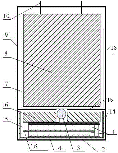
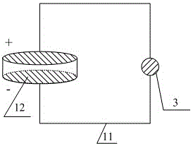
[0032] combine figure 1 Shown: a miniature thermal battery activation device, including piezoelectric ceramic sheet 1, electrode 2, electric ignition head 3, insulating layer 4, insulated wire 5, gravity block 6, ignition strip 7, single battery 8, shell Body 9, battery electrode 10, piezoelectric ceramic stack 12;
[0033] The housing 9 is configured as a cylinder, and the housing 9 is configured as an upper layer 13 and a lower layer 14,
[0034] The upper layer 13 is provided with a single battery 8 inside, the top of the single battery 8 is provided with a battery electrode 10 upward, and the outer wall and bottom end of the single battery 8 are provided with an ignition strip 7,
[0035] The lower layer 14 is sequ...
PUM
Property
Measurement
Unit
thickness
aaaaa
aaaaa
Abstract
The invention relates to a microminiature activating device for thermal batteries. The microminiature activating device comprises piezoelectric ceramic plates, electrodes, an electric ignition head, an insulating layer, an insulated conductor, a gravitational block, ignition bars, a monomer cell, a shell body, cell poles, conducting wires and a piezoelectric ceramic reactor, wherein the shell body is divided into an upper layer and a lower layer, the monomer cell is arranged inside the upper layer, the cell poles are upwards arranged at the top end of the monomer cell, the ignition bars are arranged on the external wall and bottom end of the monomer cell, and the gravitational block, the insulating layer, the electrodes and the piezoelectric ceramic plates are sequentially arranged in the lower layer from top to bottom; the gravitational block is cylindrical, a circular through hole is formed in the middle of the gravitational block, the electric ignition head is arranged inside the circular through hole, an interlayer is arranged between the upper layer and the lower layer, and an opening is formed in the middle of the interlayer. According to the microminiature activating device for the thermal batteries, the piezoelectric ceramic plates are adopted as an activating energy source, the level of integration is high, the reliability of activation reaches 99.5% or more, and the reliability is good; compared with the existing activation modes, the microminiature activating device has the advantages of low space usage and low manufacturing cost.
Description
technical field [0001] The invention belongs to the technical field of fuzes, missiles and aerospace thermal batteries, and in particular relates to a miniature thermal battery activation device. Background technique [0002] Thermal battery is a battery activated by heating, mainly composed of substrate, positive electrode sheet, negative electrode sheet, electrolyte sheet, current collector, heating system, insulation gasket, battery case, battery cover with terminal, etc. At room temperature, the electrolyte inside the thermal battery is a non-conductive solid, and the electrode active material and the electrolyte do not undergo chemical reactions with each other, and are in a non-working state. Once put into use, as long as the activation signal is input to activate the battery, the internal temperature of the battery will rise rapidly through the heating system, the electrolyte will melt to form an ion conductor with high conductivity, and the positive and negative elec...
Claims
Application Information
Patent Timeline
Application Date:The date an application was filed.
Publication Date:The date a patent or application was officially published.
First Publication Date:The earliest publication date of a patent with the same application number.
Issue Date:Publication date of the patent grant document.
PCT Entry Date:The Entry date of PCT National Phase.
Estimated Expiry Date:The statutory expiry date of a patent right according to the Patent Law, and it is the longest term of protection that the patent right can achieve without the termination of the patent right due to other reasons(Term extension factor has been taken into account ).
Invalid Date:Actual expiry date is based on effective date or publication date of legal transaction data of invalid patent.