Supercharge Your Innovation With Domain-Expert AI Agents!

Harmonic beat electric linear impact device

An impact device and a straight line technology, applied in the field of electrical engineering, can solve the problems of increasing structural volume, self-weight manufacturing material consumption and power loss, inability to stabilize the harmonic impact work, and difficulty in achieving harmonic conditions, etc.

Active Publication Date: 2017-05-17
邢台旭力机电科技有限公司
View PDF5 Cites 4 Cited by
  • Summary
  • Abstract
  • Description
  • Claims
  • Application Information

AI Technical Summary

Problems solved by technology

In practical application, it is not easy to realize the condition of harmonious shooting when the impact frequency is high or the change of rebound force of each collision is greatly different. When the impact frequency is high, the beat is lost, and the harmonic beat impact work cannot be stabilized
[0004] In the above device, both the fixed iron core coil and the movable iron core coil are sleeved on the poles of the iron core, and the wires of the fixed iron core coil and the movable iron core coil pass through the iron core horizontally around the center of the pole. The upper wire groove and the left and right sides of the electromagnetic pole are bypassed in the axial direction to form a loop. The current in the wire passing through the upper wire groove of the iron core generates electromotive force, and the electric force generated by the current in the wire bypassing the left and right sides of the electromagnetic pole in the axial direction The power cancels each other out, and it is necessary to leave space for winding the coil wires on both sides of the electromagnetic poles of the iron core along the axial direction. The power cancels out each other without force, and only plays the role of the conductive loop of the coil. The coil has wires wound along the axial direction, which increases the volume, self-weight, manufacturing material consumption and power loss of the structure.

Method used


Image

  • Harmonic beat electric linear impact device
  • Harmonic beat electric linear impact device
  • Harmonic beat electric linear impact device

Examples


Embodiment Construction

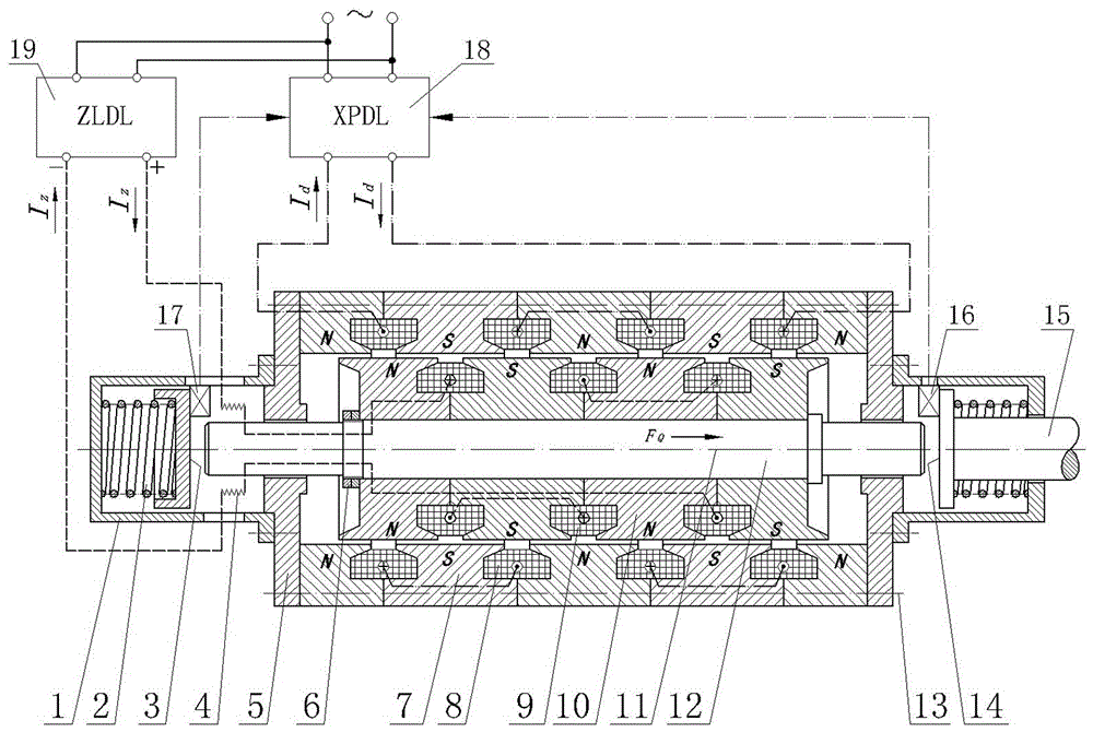
[0082] Such as figure 1As shown, the electric linear impact device shown in the figure is a side sectional view on the shaft centerline. The cylindrical iron core is composed of annular iron core segments 7 connected in series along the axial direction 11, the inner diameter surface of each annular iron core segment 7 forms the through-hole surface of the cylindrical iron core, and the line between the butt joint surfaces of the annular iron core segments 7 There is a first coil 8 in the slot, and the direction of the current in the adjacent first coil 8 along the axial direction 11 is opposite. There is a "+" in the circle in the coil section in the figure, which means that the current flows from top to bottom on the figure. , there is a "·" in the circle in the coil cross-section, indicating that the current flows from the bottom to the top of the drawing; on the through-hole surface of the cylindrical iron core, the electromagnetic polarity generated by the first coil 8 on...


PUM


Abstract

The invention relates to a harmonic beat electric linear impact device, which comprises a cylindrical iron core, a columnar iron core, a shaft rod, a shell and a harmonic beat current coil, wherein the iron core is a multi-section annular electrode; the coil is arranged annularly and transversely; one of the cylindrical iron core and the columnar iron core is a magnetizer provided with the harmonic beat current coil, and the other one is a permanent magnet or a magnetizer provided with a DC coil; the magnetizer iron core is formed by adopting a method such as cast aluminum to solidify a silicon steel sheet laminate group, the structure is simple and compact, the manufacturing materials are few consumed, the harmonic beat current circuit is controlled by a sensor to provide power for the harmonic beat current coil, the generated electrodynamic force and the rotor impact movement harmonic beat are synchronous, directions are consistent, the electrodynamic force and the resilience force are overlapped to directly act on the linear impact movement, magnetic flux leakage is little, the electric efficiency is high, and high-frequency impact work can be realized. The technology can be applied to impact and vibration machines such as a rock drill, a down-the-hole drill, a vibratory impact hammer, an impact drill, a nail-shooting gun, a jar, and a vibrator.

Description

technical field [0001] The invention relates to a harmonic beat electric linear impact device, which belongs to the field of electrical engineering. Background technique [0002] The invention patent named "An Electric Harmonious Shot Reciprocating Linear Motion Impact Device" (Patent No. ZL20081005453.X, Authorized Announcement No. CN101262163B, Authorized Announcement Date 2010.12.08), its structure includes a fixed iron core, a movable iron core, a fixed Iron core coil, movable iron core coil, sliding sleeve, shaft rod, punch, recoil spring device, frame and power wiring circuit, etc., the fixed iron core is fixed on the frame, and the frame on both sides of the fixed iron core There is a sliding sleeve, the movable iron core is fixed on the shaft, and the movable iron core, the coil of the movable iron core and the shaft constitute an integrated impact movement device, and the two ends of the shaft are installed on the sliding sleeves on both sides of the fixed iron core...

Claims


Application Information

Patent Timeline
IPC IPC(8): H02K33/16
CPCH02K33/16
Inventor 张胜田
Owner 邢台旭力机电科技有限公司
Features
  • R&D
  • Intellectual Property
  • Life Sciences
  • Materials
  • Tech Scout
  • Unparalleled Data Quality
  • Higher Quality Content
  • 60% Fewer Hallucinations
Learn More