Inner-magnet moving-coil speaker multi-channel magnetic circuit system

A magnetic circuit system and multi-channel technology, applied in the field of loudspeakers, can solve the problems of disturbing the normal movement of the diaphragm, burning out the voice coil, and uneven heat dissipation of the system as a whole, so as to optimize the electro-acoustic performance and application performance, and increase the heat dissipation scale. , The effect of uniform heat dissipation area

Inactive Publication Date: 2017-05-17
王卫平
View PDF4 Cites 3 Cited by
  • Summary
  • Abstract
  • Description
  • Claims
  • Application Information

AI Technical Summary

Problems solved by technology

[0003] When the magnetic circuit system of the moving coil loudspeaker is doing work, the vibration of the voice coil in the magnetic air gap, especially in the state of large amplitude, will generate a lot of heat energy. This heat energy will not only increase the impedance of the voice coil, but also cause the magnetic air gap When the air in the magnetic air gap is heated, the air in the magnetic air gap will be heated to the entire magnetic circuit system, which is equivalent to the temperature rise of the entire magnetic circuit system. In this state, the magnetic domain disorder, magnetic resistance increase, and magnetic force unevenness will occur in the magnetic circuit system. Magnetic weakening and other phenomena, these phenomena weaken the driving force and control force of the magnetic circuit on the voice coil, causing the power load of the voice coil to decrease, resulting in distortion of the vibration system
If the magnetic field is severely weakened, the voice coil will burn out the circuit due to high temperature and high resistance, and completely damage the speaker to work.
Therefore, some current speakers have a through hole axially opened in the center of the magnetic circuit system to allow the air flow driven by the up and down vibration of the voice coil and the up and down movement of the diaphragm to dissipate heat, so as to reduce the heat effect of the magnetic circuit system when it does work, so as to ensure The normal work of the magnetic circuit system, but this method not only has a very limited heat dissipation scale, but also has uneven heat dissipation for the entire magnetic circuit system: when the voice coil heats up and affects the overall temperature rise of the magnetic circuit system, only the magnetic circuit system close to the air convection magnetic The heat dissipation of the air gap part is better, and the heat dissipation of the part farther away from the magnetic air gap is poorer. Although the degree of suppression of magnetic domain disorder, increased reluctance, uneven magnetic force, and weakened magnetic force has been alleviated, it will still be to a certain extent. There is a situation that the temperature control of the magnetic circuit system is not enough to affect the distortion of the speaker
[0004] In addition to the above-mentioned defects, there is another important defect: even if it is an internal magnetic type or an external magnetic type moving coil speaker with a center hole, the large part of the surface of the magnetic circuit system that is not perforated will displace the back of the speaker diaphragm. Sound waves (especially sound waves above 400Hz) are reflected back to the diaphragm, and the sound energy of the reflected wave will interfere with the normal movement of the diaphragm, resulting in modulation distortion of the speaker vibration system
The Reynolds number generated by the magnetic circuit without holes is larger than that of the hole, and the scale of turbulence is also larger; installed behind the speaker box, the speaker magnetic circuit with only one middle hole is currently better than the unopened speaker magnetic circuit in terms of aerodynamics. Hole magnetic circuit, but its air flow resistance area is still too large, and it has not yet reached the best way to solve the problem of turbulence caused by the loudspeaker magnetic circuit system

Method used


Image

  • Inner-magnet moving-coil speaker multi-channel magnetic circuit system
  • Inner-magnet moving-coil speaker multi-channel magnetic circuit system
  • Inner-magnet moving-coil speaker multi-channel magnetic circuit system

Examples


Embodiment 1

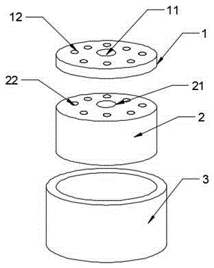
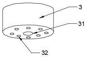
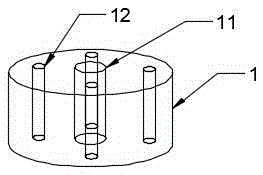
[0021] see Figure 1-3 , a multi-channel magnetic circuit system for an internal magnetic moving coil speaker, comprising a multi-channel magnetic plate 1, a multi-channel magnet 2 and a multi-channel magnetic bowl 3, the multi-channel magnetic plate 1 is made of low-carbon steel or the like A circular cake shape made of magnetic material that passes through multiple channels. The multi-channel magnet 2 is a cylindrical shape with multiple channels made of NdFeB material. The multi-channel magnetic conduction bowl 3 is made of low carbon steel, etc. The shape of a round cup made of a magnetically conductive material that passes through multiple channels; the multi-channel magnet 2 is arranged in the multi-channel magnetic conduction bowl 3, the multi-channel magnetic plate 1 is arranged on the multi-channel magnet 2, and the multi-channel magnet The magnetic plate 1, the multi-channel magnet 2 and the multi-channel magnetic bowl 3 are all provided with a plurality of through h...

Embodiment 2

[0025] see figure 1 , 2 , 4, a multi-channel magnetic circuit system of an internal magnetic moving coil speaker, the difference from Embodiment 1 is that the central axis of the multi-channel magnetic plate 1 is provided with a central through hole 11 of the magnetic plate, and the magnetic plate There are six magnetic plate side holes 12 evenly distributed around the central hole 11; the central axis of the multi-channel magnet 2 is provided with a magnet center through hole 21, and six magnet side holes 22 are evenly distributed around the magnet center through hole 21; A central through hole 31 is arranged in the center of the bottom of the multi-channel magnetic conductive bowl 3 , and six side holes 32 are distributed around the central through hole 31 of the magnetic conductive bowl.

Embodiment 3

[0027] see figure 1 , 2 , 5, a multi-channel magnetic circuit system of an internal magnetic moving coil speaker, the difference from Embodiment 1 is that the central axis of the multi-channel magnetic plate 1 is provided with a central through hole 11 of the magnetic plate, and the magnetic plate There are eight magnetic plate side holes 12 evenly distributed around the center hole 11; the central axis of the multi-channel magnet 2 is provided with a magnet center through hole 21, and eight magnet side holes 22 are evenly distributed around the magnet center through hole 21; The central through-hole 31 of the center of the bottom of the multi-channel magnetic bowl 3 is axially provided with a central through hole 31 of the magnetic bowl, and eight side holes 32 of the magnetic bowl are distributed around the central through hole 31 of the magnetic bowl.

[0028] The present invention improves the performance of the current magnetic circuit that only has one hole in the axial...


PUM


Abstract

The invention discloses an inner-magnet moving-coil speaker multi-channel magnetic circuit system. The system comprises a multi-channel magnetic plate, a multi-channel magnet, and a multi-channel magnetic bowl. The multi-channel magnetic plate is shaped as a round disk made of a magnetic material and punching through multiple channels. The multi-channel magnet is shaped as a cylinder made of a magnetic material and punching through multiple channels. The multi-channel magnetic bowl is shaped as a round cup made of a magnetic material and punching through multiple channels. The multi-channel magnet is arranged in the multi-channel magnetic bowl. The multi-channel magnetic plate is arranged on the multi-channel magnet. The multi-channel magnetic plate, the multi-channel magnet and the multi-channel magnetic bowl are provided with multiple punch-through channels of the same coordinate and same diameter. The heat dissipation area of the magnetic circuit system is uniform. The magnetic stability is improved. The interference of the reflected sound wave of surface area of the magnetic circuit system to normal movement of a vibrating diaphragm is reduced. The Reynolds number caused by air disorder of the magnetic circuit system is reduced. Therefore, the causes of turbulent flow are reduced greatly.

Description

technical field [0001] The invention relates to the technical field of loudspeakers in audio and video, in particular to a multi-channel magnetic circuit system of an inner magnetic moving coil loudspeaker. Background technique [0002] At present, regardless of the external magnetic circuit (the magnet is located outside the voice coil) or the internal magnetic circuit (the magnet is located inside the voice coil), the channel of the moving coil speaker magnetic circuit system is set in the center of the magnetic circuit. A through hole is arranged axially. [0003] When the magnetic circuit system of the moving coil loudspeaker is doing work, the vibration of the voice coil in the magnetic air gap, especially in the state of large amplitude, will generate a lot of heat energy. This heat energy will not only increase the impedance of the voice coil, but also cause the magnetic air gap When the air in the magnetic air gap is heated, the air in the magnetic air gap will be h...

Claims


Application Information

Patent Timeline
Patent Type & Authority Applications(China)
IPC IPC(8): H04R9/06H04R9/02
Inventor 陈东红
Owner 王卫平
Why Eureka
Try Eureka