
Piezoelectric element-driven valve and flow-rate control device including piezoelectric element-driven valve

A technology of flow control device and piezoelectric element, applied in non-electric variable control, piezoelectric device/electrostrictive device, flow control and other directions, can solve the damage of piezoelectric element, trouble in assembly, increase piezoelectric actuator Stroke and other issues, to achieve the effect of increasing displacement and easy assembly

Inactive Publication Date: 2017-05-17
FUJIKIN INC
View PDF12 Cites 3 Cited by
  • Summary
  • Abstract
  • Description
  • Claims
  • Application Information

AI Technical Summary

Problems solved by technology

[0008] However, in the above-mentioned piezoelectric element-driven valve, it is necessary to incorporate a displacement expansion mechanism with a complicated structure between the piezoelectric actuator and the valve stem, which causes other troublesome problems such as assembly.
[0009] On the other hand, in order to increase the displacement of the piezoelectric element and increase the stroke of the piezoelectric actuator, any piezoelectric element-driven valve with a structure in which two piezoelectric actuators are stacked up and down is sufficient. However, The status quo is that such piezo-actuated valves have not yet been developed
[0010] Furthermore, simply stacking two piezoelectric actuators on top of each other will cause problems in wiring etc.
[0011] In addition, although the stroke can be increased by making a long piezoelectric actuator, in the piezoelectric actuator of the multilayer piezoelectric element type, there is a problem in that when the piezoelectric element is elongated, the pressure will be reduced. The entire electrical element may be bent, making it impossible to manufacture a long piezoelectric actuator with good precision
Furthermore, the problem is that when the piezoelectric element is elongated, it becomes weak against external force from the lateral direction (direction perpendicular to the axis), and the piezoelectric element is easily damaged by impact from the lateral direction.

Method used


Image

  • Piezoelectric element-driven valve and flow-rate control device including piezoelectric element-driven valve
  • Piezoelectric element-driven valve and flow-rate control device including piezoelectric element-driven valve
  • Piezoelectric element-driven valve and flow-rate control device including piezoelectric element-driven valve

Examples


Embodiment Construction

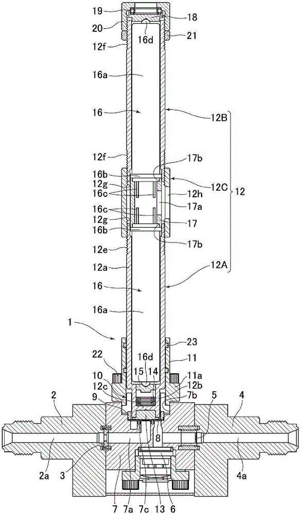
[0109] Hereinafter, embodiments of the present invention will be described in detail based on the drawings.

[0110] figure 1 A flow rate control device including a piezoelectric element-driven valve 1 according to an embodiment of the present invention is shown. The flow rate control device includes: a piezoelectric element-driven valve 1; As shown in the figure) is screwed and fixed on the upstream side of the main body 7 of the piezoelectric element-driven valve 1, and an inlet-side fluid passage 2a communicating with the fluid passage 7a of the main body 7 is formed; the gasket 3 for sealing is interposed (inserted) Provided between) the main body 7 and the inlet side block 2; the outlet side block 4, which is screwed and fixed on the downstream side of the main body 7 of the piezoelectric element-driven valve 1 by bolts (not shown), and is formed with the main body The outlet-side fluid passage 4a communicated with the fluid passage 7a of 7; the washer-type orifice 5 (o...


PUM


Abstract

The present invention provides: a piezoelectric element-driven valve in which the amount of displacement of a piezoelectric element can be increased without using a complicated mechanism, and in which wiring lines etc. are not impaired; and a flow-rate control device including said piezoelectric element-driven valve. The present invention is a piezoelectric element-driven valve 1 comprising: a main body 7 provided with a fluid passage 7a and a valve seat 7c; a valve body 8 that opens and closes the fluid passage 7a by coming into contact with and separating from the valve seat 7c of the main body 7; and piezoelectric actuators 16 each driving the valve body 8 so as to open and close by utilizing the extension of a piezoelectric element. At least two piezoelectric actuators 16 are arranged along a single straight line with a spacer 17 therebetween from which a wiring line can be drawn out.

Description

technical field [0001] The present invention relates to a piezoelectric element-driven valve that is installed on a fluid supply line of semiconductor manufacturing equipment, chemical industry equipment, pharmaceutical industry equipment, food industry equipment, etc. Improvement of a control device, particularly a piezoelectric element-actuated valve capable of increasing the displacement of the piezoelectric element without causing obstacles to wiring, etc., and a flow control device equipped with a piezoelectric element-actuated valve . Background technique [0002] At present, piezoelectric element-driven valves and flow control devices equipped with piezoelectric element-driven valves are widely used in fluid supply lines such as semiconductor manufacturing equipment and chemical industry equipment (for example, refer to Invention Patent Document 1, Invention Patent Document 2 , Invention Patent Document 3, Invention Patent Document 4, Invention Patent Document 5, Inv...

Claims


Application Information

Patent Timeline
Patent Type & Authority Applications(China)
IPC IPC(8): F16K31/02F16K7/14H01L41/053H01L41/083H01L41/09
CPCF16K7/16F16K31/007G05D7/0635H10N30/886H10N30/50F16K7/14F16K31/004H10N30/88H10N30/20
Inventor 平田薰杉田胜幸土肥亮介西野功二池田信一
Owner FUJIKIN INC
Features
  • Generate Ideas
  • Intellectual Property
  • Life Sciences
  • Materials
  • Tech Scout
  • Unparalleled Data Quality
  • Higher Quality Content
  • 60% Fewer Hallucinations
Learn More