Personalized pedicle screw drilling template with quick-change drill sleeve and its preparation method

A pedicle and screw placement technology, applied in the field of medical devices, can solve the problems of easy wear and melting of catheters, expensive navigation equipment, lack of effective theory and means for pedicle screw placement channel planning, etc., to ensure accuracy. and safety, excellent biomechanical properties, firm three-dimensional fixation effect

Active Publication Date: 2017-11-10
NANHUA UNIV
View PDF7 Cites 0 Cited by
  • Summary
  • Abstract
  • Description
  • Claims
  • Application Information

AI Technical Summary

Problems solved by technology

In recent years, the computer navigation method has been gradually applied in the internal fixation of pedicle screws. It uses real-time pedicle image information of patients to guide the operation, which reduces the risk of surgery and reduces the time for both doctors and patients to be exposed to radiation. It has great advantages. However, navigation equipment is expensive and complicated to operate, and there are still difficulties in clinical popularization
The navigation template method is to manufacture a navigation template based on 3D printing technology, which has the advantages of quick response to surgery and cost-effectiveness. The current individualized navigation template mainly has three problems: first, the template is thin and rigid, which is inconvenient. During the operation, the template is easy to deform and shake when drilling; the second is that the catheter of the navigation template without a sleeve is easy to wear and melt, while the navigation template with a sleeve has a clearance fit between the sleeve and the template and relative rotation , which will affect the orientation accuracy and use effect; the third is that the planning of pedicle screw placement channel lacks effective theoretical and means support, and its optimization method, work efficiency and planning effect need to be improved

Method used


Image

  • Personalized pedicle screw drilling template with quick-change drill sleeve and its preparation method
  • Personalized pedicle screw drilling template with quick-change drill sleeve and its preparation method
  • Personalized pedicle screw drilling template with quick-change drill sleeve and its preparation method

Examples


Embodiment 1

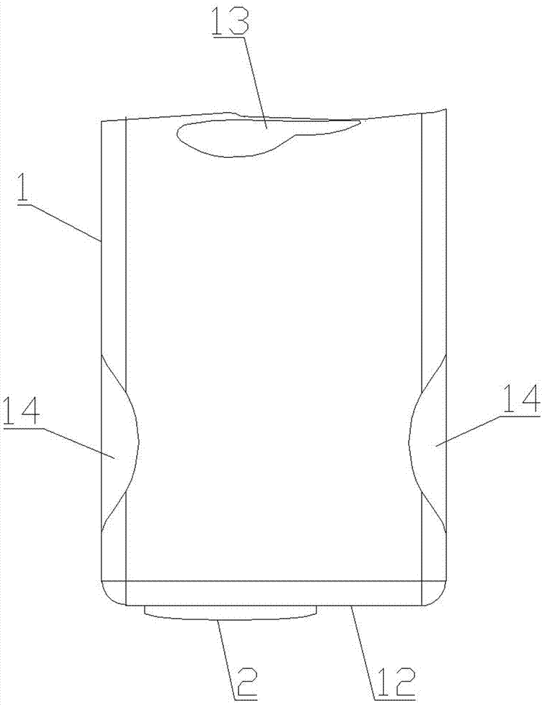
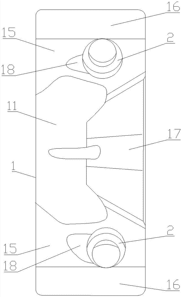
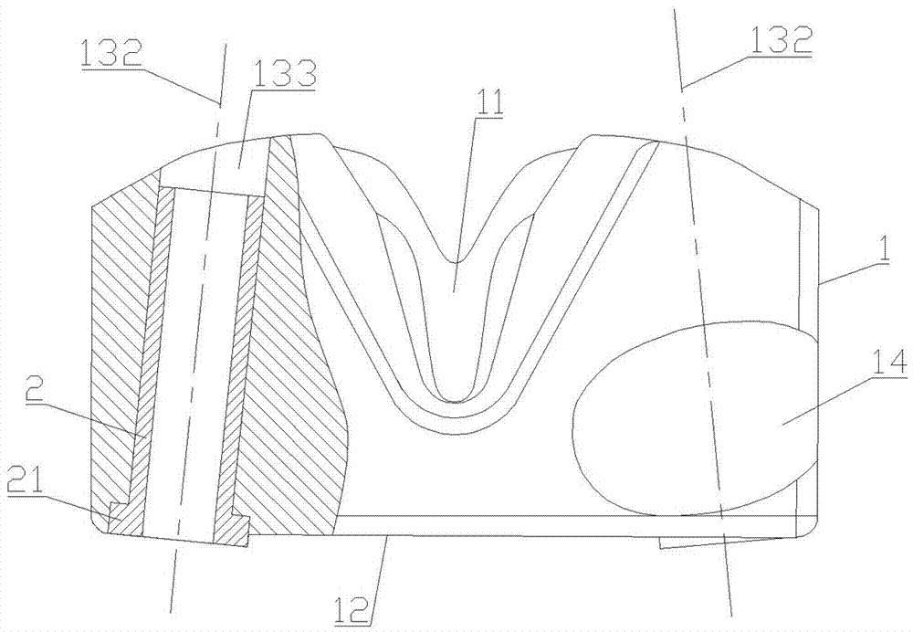
[0049] Such as Figure 1~6 As shown, the personalized pedicle screw drilling template with quick-change drill sleeves includes the main body 1 and the drill sleeve 2.

[0050] The lower end of the body 1 is provided with a bone fitting surface 11 and a bottom surface 15 , and the upper end is provided with a nail placement plane 12 . The main body is provided with two nail placement channels 13 , one end of the nail placement channel 13 runs through to the nail placement plane 12 , and the other end runs through to the bottom surface 15 . The bone-fitting surface 11 adheres to and coincides with the contours of the lamina of the target vertebra 31 , the posterior portion of the transverse process, and the dorsal side of the root of the spinous process. When the bone-fitting surface 11 is attached and coincident with the target vertebra 31 , the central axis 132 of the nail placement channel 13 coincides with the central axis of the largest inscribed elliptical cylinder of the...


PUM


Abstract

A personalized pedicle screw drilling mold with quick-change drill sleeves and a preparation method thereof. The personalized pedicle screw drilling mold includes a body and a drill sleeve; There is a nailing plane, and there are finger pressure pits on the front and rear side walls. There are two nailing channels in the body. One end of the nailing channel is connected to the nailing plane, and the other end is connected to the bottom surface; the drill sleeve is installed in the nailing channel. , they form a transition fit. The advantage of the present invention is that the structural size and the bone-fitting surface of the body are designed according to the shape and size of the target vertebra and the positional relationship with adjacent vertebrae, which has obvious characteristics of personalized customization. Drill the threaded bottom hole of the pedicle screw through the drill sleeve, and then implant the pedicle screw, which can not only ensure that the pedicle cortex is not pierced, but also ensure that the screw has a larger diameter within the range allowed by the pedicle space. Diameter, so as to ensure a firm three-dimensional fixation effect after implantation to the greatest extent, and realize the reproduction of the biomechanical characteristics of the vertebral joint.

Description

technical field [0001] The invention relates to the technical field of medical devices, in particular to a personalized pedicle screw drill template with a quick-change drill sleeve and a preparation method thereof. Background technique [0002] The surgical indications for pedicle screw internal fixation are suitable for spinal cord tumors, degenerative diseases, rheumatoid arthritis and infectious diseases, especially in the treatment of spondylolisthesis reduction and correction surgery, transpedicular internal fixation is the The most reliable fixation method. Because pedicle screws can play a three-dimensional fixation role, have the advantages of high mechanical strength, fewer fixation and fusion segments, and better correction of spinal deformity, their clinical application is becoming more and more extensive. [0003] Biomechanical experiments have proved that the ideal clinical effect can only be obtained if the screw is placed along the anatomical long axis of th...

Claims


Application Information

Patent Timeline
Patent Type & Authority Patents(China)
IPC IPC(8): A61B17/70A61B17/92
CPCA61B17/7076A61B17/90
Inventor 胡良斌李必文秦元帅邓骞李军周炬谭文甫
Owner NANHUA UNIV
Why Eureka
Try Eureka