
Non-uniform electrostatic field efficient impurity removing equipment

An electrostatic field and non-uniform technology, which is applied in the field of high-efficiency impurity removal equipment for non-uniform electrostatic fields, can solve the problems of inability to remove neutral impurities in oil, unfavorable equipment use safety, and poor purification effect, etc., to achieve simple structure and easy to use The effect of long life and stable quality

Inactive Publication Date: 2017-05-24
CHONGQING UNIVERSITY OF SCIENCE AND TECHNOLOGY
View PDF6 Cites 3 Cited by
  • Summary
  • Abstract
  • Description
  • Claims
  • Application Information

AI Technical Summary

Problems solved by technology

If the traditional plate structure relies on two plates to generate a uniform electric field, the charged impurities are adsorbed to the plate to achieve the effect of impurity removal, but it does not attract the neutral impurities in the liquid, so that the neutral impurities in the oil cannot be removed. Sexual impurities, so the purification effect is not very good
[0005] In order to obtain a non-uniform electric field, we can add a dielectric to the electric field, or change the structure. If the dielectric is used, it needs to be replaced for a long time according to the flow of the fluid. Although the cylindrical structure device of the electric field can generate a non-uniform electric field, the electric field intensity and the magnitude of the electric field gradient decrease sharply with the distance between the center electrode and the shell electrode, and only the electric field intensity and gradient near the center electrode are relatively large , so in order to exert a good impurity removal effect, a very high electric field must be applied, which will cause qualitative changes in the liquid flowing through the device under the action of a high electric field, which is not conducive to the safety of the equipment

Method used


Image

  • Non-uniform electrostatic field efficient impurity removing equipment
  • Non-uniform electrostatic field efficient impurity removing equipment
  • Non-uniform electrostatic field efficient impurity removing equipment

Examples


Embodiment Construction

[0028] The present invention will be described in further detail below in conjunction with the accompanying drawings and specific embodiments.

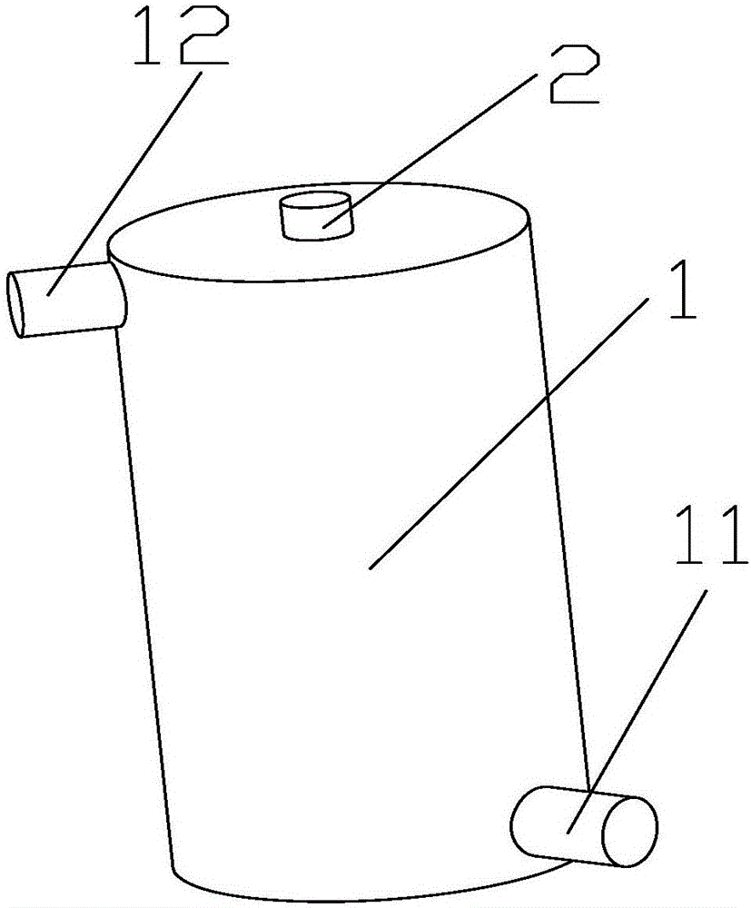
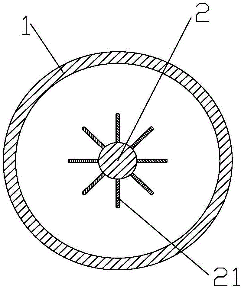
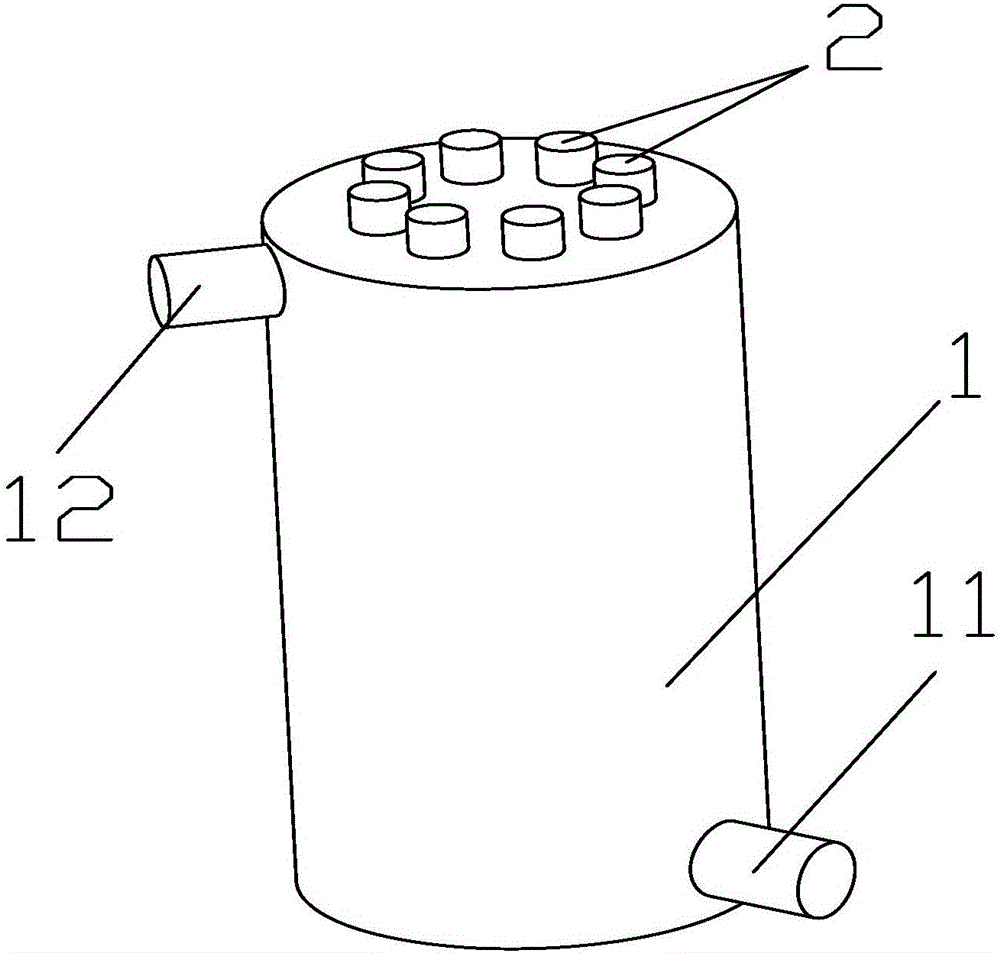
[0029] refer to figure 1 and figure 2 The first embodiment of the non-uniform electrostatic field high-efficiency impurity removal device shown includes a closed cylindrical shell 1. In this embodiment, the shell 1 is made of conductive material, and it can also be directly placed on a non-conductive material in actual use. The insulating material is directly evaporated on the top, the lower part of the casing 1 is provided with an inlet 11 communicating with the interior of the casing, and the upper part is provided with an outlet 12 communicating with the interior. The inlet 11 and the outlet 12 are preferably located on different semicircle outer walls of the casing 1 , preferably the projected distance between the two on the horizontal plane is equal to the diameter of the shell 1, so that the flow stroke of the fluid flowing in...


PUM


Abstract

The invention discloses non-uniform electrostatic field efficient impurity removing equipment. The non-uniform electrostatic field efficient impurity removing equipment comprises a shell of a cylindrical structure. The shell is energized to form a first electrode. An inlet is formed in the lower end of the shell, and an outlet is formed in the upper end of the shell. The shell is internally provided with at least one conductive rod. The conductive rods are arranged in the axial direction of the shell and are energized to form center electrodes. Conductive protrusions are uniformly distributed on the outer surface of each conductive rod and outwards extend in the radial direction of the conductive rod, and gaps are reserved between the conductive protrusions and the inner wall of the shell. By means of the structure, the outwards protruding conductive protrusions are uniformly arranged on the conductive rods, and a non-uniform electrostatic field is formed in the shell; meanwhile, the outward attenuation degree of the electrostatic field is effectively alleviated, and the intensity of the electrostatic field is relatively improved; the conductive protrusions and the shell are matched to conduct stable purifying and impurity removing on flowing fluid, the equipment impurity removing efficiency of the non-uniform gradient electrostatic field is improved, and pure fluid stable in quality is finally obtained; and the non-uniform electrostatic field efficient impurity removing equipment is simple in structure and long in service life and has great practical and economic value.

Description

technical field [0001] The invention belongs to the field of fluid purification equipment, and in particular relates to a non-uniform electrostatic field efficient impurity removal equipment. Background technique [0002] With the improvement of living standards, people pay more and more attention to the environment, which requires higher and higher requirements for various purification devices. The air contains a variety of pollutants, such as PM2.5, dust particles, and allergens, etc., and many unmanned gases in the air are mostly exhaust gases from vehicles, many of which are impurities in the fuel that are not burned together with the exhaust gas Emissions into the atmosphere will greatly affect the air quality and the life of the combustion equipment. [0003] In particular, petroleum contains harmful impurities such as sulfur, nitrogen, oxygen compounds and trace metals. The presence of impurities will accelerate the corrosion of equipment during use, affect the norma...

Claims


Application Information

Patent Timeline
Patent Type & Authority Applications(China)
IPC IPC(8): B03C5/02
CPCB03C5/022B03C2201/08
Inventor 高荣礼白守勇符春林蔡苇陈刚邓小玲王凤起张鲸
Owner CHONGQING UNIVERSITY OF SCIENCE AND TECHNOLOGY
Learn More