Automatic plastic film cutting device

An automatic cutting device and plastic film technology, applied in metal processing, etc., can solve the problems of reducing work efficiency, affecting production progress, and cutting devices cannot continue cutting work, and achieve the effect of improving precision and facilitating cutting work

Active Publication Date: 2017-05-24
CHONGQING RUITING PLASTIC
View PDF5 Cites 6 Cited by
  • Summary
  • Abstract
  • Description
  • Claims
  • Application Information

AI Technical Summary

Problems solved by technology

[0002] At present, in the existing lost foam casting process, when working, after the finished mold is loaded into the sand box, the sand box moves forward, and the front sand box drags the plastic film to move forward. When it moves to the sand adding equipment , start to add sand to the sand box, the sand box after adding sand needs to be covered with a plastic film on the mouth of the sand box to seal, the plastic film needs to be cut into a fixed size when covering, and the automatic cutting device of the cylinder is used in the prior art. Plastic film is cut, but compressed air is needed when the cylinder is working. When the supply of compressed air is insufficient, the production progress will be affected, resulting in the cutting device not being able to cut continuously, thereby reducing work efficiency.

Method used


Image

  • Automatic plastic film cutting device
  • Automatic plastic film cutting device
  • Automatic plastic film cutting device

Examples


Embodiment Construction

[0017] The present invention is described in further detail below by specific embodiments:

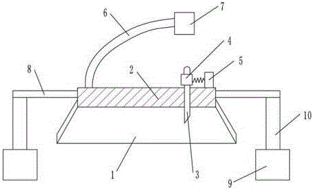
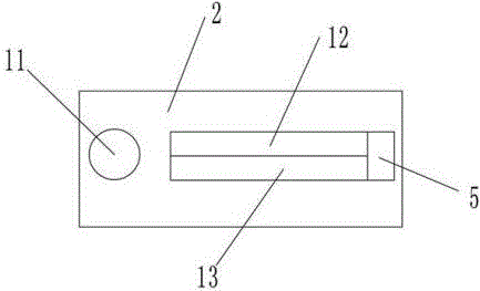
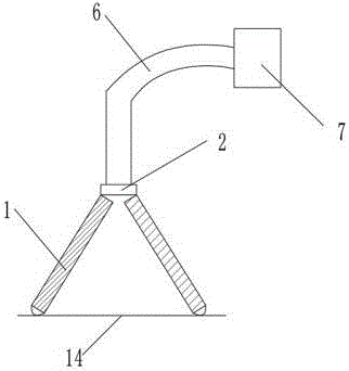
[0018] The reference signs in the drawings include: baffle 1, cover plate 2, blade 3, magnet 4, electromagnet 5, suction pipe 6, suction pump 7, bracket 8, cylinder 9, piston rod 10, suction port 11. The first flexible board 12 , the second flexible board 13 , and the plastic film 14 .

[0019] The example is basically as attached figure 1 Shown: an automatic cutting device for plastic films, including a cutting knife and several baffles 1, the cutting knife includes a handle and a blade 3, a magnet 4 is arranged on the handle, the blade 3 is in the shape of a cone, and the top of the baffle 1 is sealed with a The cover plate 2, the bottom plate of the baffle plate 1 is placed with a plastic film 14, the left end of the cover plate 2 is provided with a suction pipe 6, the suction pipe 6 is provided with an air suction pump 7, the right end of the cover plate 2 is fixed with an electro...


PUM


Abstract

The invention belongs to the field of evaporative pattern casting machines, and concretely discloses an automatic plastic film cutting device, which comprises a cutting knife and a plurality of baffle plates. A covering plate is sealed on the baffle plates; a knife slot is formed in the covering plate; a first flexible plate and a second flexible plate which are opposite are horizontally arranged on the knife slot; an air suction pipe is arranged at one end of the covering plate; a sucking pump is arranged on the air suction pipe; an electromagnet is fixedly arranged at the other end of the covering plate; a magnet is arranged on a knife handle; supports are arranged at two sides of the covering plate; air cylinders are arranged under the supports, and are provided with piston rods; and the piston rods are connected with the supports. The invention provides the automatic plastic film cutting device capable of continuously automatic cutting plastic films.

Description

technical field [0001] The invention relates to the field of lost foam casting machinery. Background technique [0002] At present, in the existing lost foam casting process, during work, after the finished mold is loaded into the sand box, the sand box moves forward, and the frontmost sand box drags the plastic film forward, and when it moves to the sand adding equipment , start adding sand to the sand box, the sand box after sanding needs to be covered with plastic film on the sand box mouth to seal, and the plastic film needs to be cut into a fixed size when covering. Plastic film is cut, but compressed air is needed when the cylinder is working. When the compressed air supply is insufficient, it will affect the production progress and cause the cutting device to not be able to continuously cut the work, thereby reducing the work efficiency. SUMMARY OF THE INVENTION [0003] The purpose of the present invention is to provide an automatic cutting device for plastic film...

Claims


Application Information

Patent Timeline
Patent Type & Authority Applications(China)
IPC IPC(8): B26D1/06B26D7/08
CPCB26D1/065B26D7/08
Inventor 毛德中
Owner CHONGQING RUITING PLASTIC
Why Eureka
Try Eureka