
Material transportation flow line system on basis of linear motor drive

A linear motor, logistics transmission technology, applied in mechanical conveyors, conveyor objects, conveyors, etc., can solve problems such as low energy efficiency, difficulty in production line precision meeting predetermined requirements, and inconvenient control.

Inactive Publication Date: 2017-05-24
SHANGHAI DIANJI UNIV
View PDF9 Cites 5 Cited by
  • Summary
  • Abstract
  • Description
  • Claims
  • Application Information

AI Technical Summary

Problems solved by technology

[0002] In today's highly developed modern industry, the production line has become an indispensable member of the energy field. Many industries, such as electrical, electronics, machinery, chemical, pharmaceutical and other production lines and assembly lines, generally use wire rope or chain transmission. The method is often noisy, slow, and inconvenient to control. Using traditional motor-driven assembly line production can achieve engineering characteristics well for general processing and production, but the energy efficiency in industrial manufacturing processes is not high. Traditional In the assembly line production process provided by the motor drive, a large part of the energy loss will be lost in the transmission process between machines, which is a great waste of energy in terms of energy; at the same time, in some specific precise processing techniques, the traditional production line It is difficult to meet the predetermined requirements. In order to better meet the requirements of more precise processing in the pouring industry and to protect the high efficiency of industrial manufacturing, linear motor-driven assembly lines have become a hot spot in the manufacturing industry.

Method used


Image

  • Material transportation flow line system on basis of linear motor drive
  • Material transportation flow line system on basis of linear motor drive
  • Material transportation flow line system on basis of linear motor drive

Examples


Embodiment Construction

[0018] In order to make the technical means, creative features, goals and effects achieved by the present invention easy to understand, the present invention will be further elaborated below in conjunction with illustrations and specific embodiments.

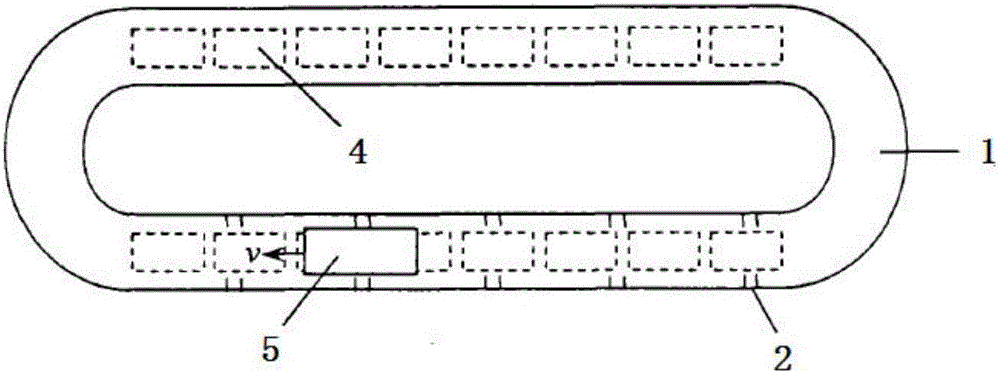
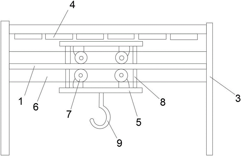
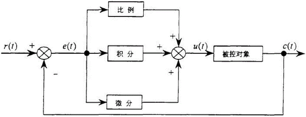
[0019] Such as Figure 1 to Figure 3 As shown, the logistics transmission assembly line system based on linear motor drive proposed by the present invention includes a logistics transmission system and a PID control system for controlling the logistics transmission system:

[0020] The logistics transmission system includes a track, a linear motor transmission system arranged on the surface of the track, and a photoelectric switch arranged on the side of the linear motor transmission system;

[0021] The linear motor transmission system includes a support, a linear motor primary part arranged inside the support, a trolley provided at the lower end of the linear motor primary part, and a track side provided at the upper and lower...


PUM


Abstract

The invention relates to a material transportation flow line system on the basis of linear motor drive. The material transportation flow line system comprises a material transportation system and a PID (proportion, integration and differentiation) control system. The PID control system is used for controlling the material transportation system, the material transportation system comprises a track, a linear motor transportation system and photoelectric switches, the linear motor transportation system is arranged on the surface of the track, and the photoelectric switches are arranged on the side surfaces of the linear motor transportation system; the linear motor transportation system comprises supports, linear motor primary components, trolleys, track side edges, wheels and rib columns, the linear motor primary components are arranged inside the supports, the trolleys are arranged at the lower ends of the linear motor primary components, the track side edges are arranged at the upper end and the lower end of the track, the wheels are arranged inside the trolleys, and the rib columns are arranged on the side surfaces of the wheels.

Description

technical field [0001] The invention relates to the field of industrial motor application control systems, in particular to a logistics transmission assembly line system driven by a linear motor. Background technique [0002] In today's highly developed modern industry, the production line has become an indispensable member of the energy field. Many industries, such as electrical, electronics, machinery, chemical, pharmaceutical and other production lines and assembly lines, generally use wire rope or chain transmission. The method is often noisy, slow, and inconvenient to control. Using traditional motor-driven assembly line production can achieve engineering characteristics well for general processing and production, but the energy efficiency in industrial manufacturing processes is not high. Traditional In the assembly line production process provided by the motor drive, a large part of the energy loss will be lost in the transmission process between machines, which is a ...

Claims


Application Information

Patent Timeline
IPC IPC(8): B65G35/06B65G43/00
CPCB65G35/06B65G43/00
Inventor 陈原曾宪文高桂革徐英杰谢涛孙博力余星儒
Owner SHANGHAI DIANJI UNIV
Learn More