A FPC coil structure with varying copper foil line width

A coil and line width technology, applied in the field of FPC coil structure, can solve problems such as large proximity effect, reduced transmission efficiency, and large magnetic field strength

Active Publication Date: 2021-05-18
ZHEJIANG DONGYANG CHENGJI ELECTRO MECHANICS CO LTD
View PDF9 Cites 0 Cited by
  • Summary
  • Abstract
  • Description
  • Claims
  • Application Information

AI Technical Summary

Problems solved by technology

[0006] An object of the present invention is to provide an FPC coil structure with a copper foil line width change, which solves the problem of the existing coil structure at the receiving end of wireless charging. The magnetic field strength near the center of the coil is the largest, resulting in a large proximity effect and increasing the AC resistance of the FPC coil. , which reduces the transmission efficiency of the defect

Method used


Image

  • A FPC coil structure with varying copper foil line width
  • A FPC coil structure with varying copper foil line width
  • A FPC coil structure with varying copper foil line width

Examples


Embodiment 1

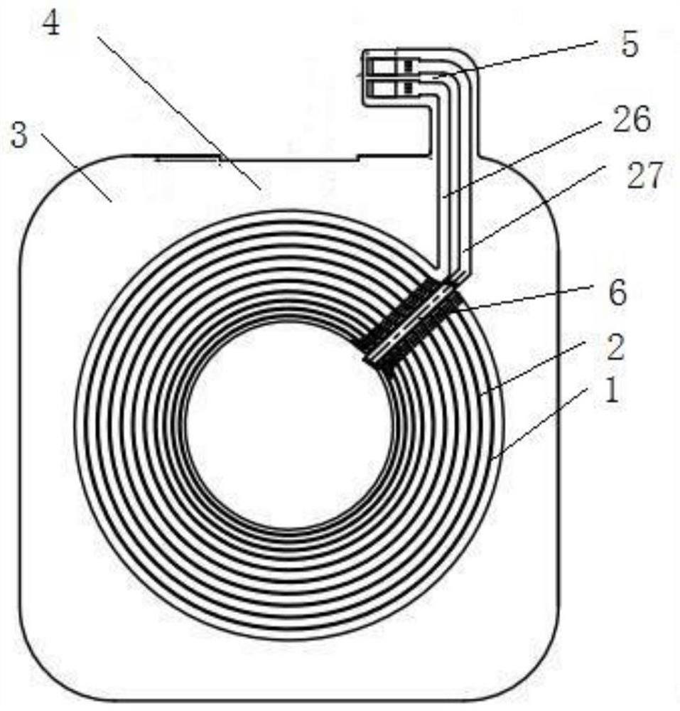
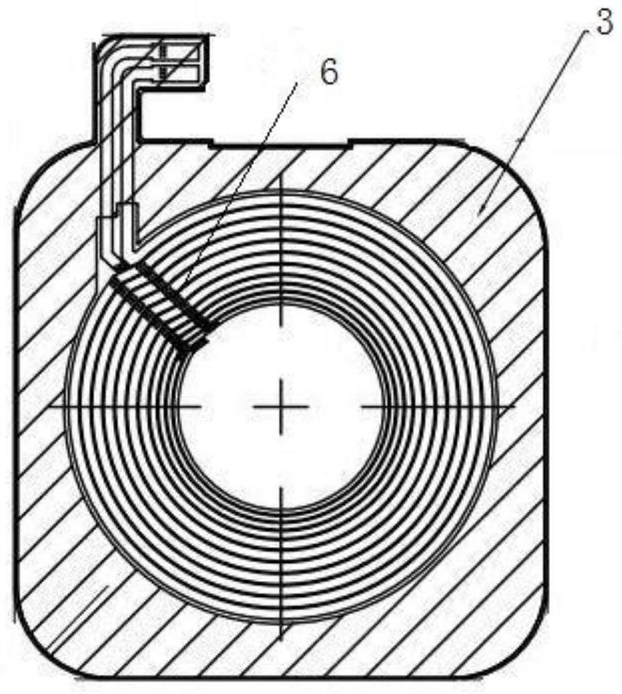
[0030] Such as figure 1 , figure 2 , image 3 As shown, the present invention provides a FPC coil structure with variable copper foil line width, comprising: a coil 2 having n turns of coil layer 1, and the width of the coil layer decreases layer by layer from the inside out. The width of any one turn of the coil layer is 0.4-1 mm. The FPC coil structure with variable copper foil line width also includes an FPC fixing plate 3 on which the coil is installed, and a protective film area 4 is installed on the fixing plate outside the coil. A protruding pad 5 is provided on one side of the FPC fixing board. The coil also has a wire slot 6 extending radially, and the coil has a wire outlet 26 and a wire inlet 27, and the wire outlet or wire inlet is installed in the wire slot. The terminal of the outgoing wire or the incoming wire is fixed in the welding pad.

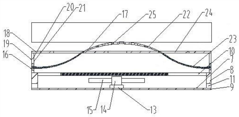
[0031] The FPC coil structure with variable copper foil line width also includes a base 7, the base includes a side w...

Embodiment 2

[0034] The present invention provides an FPC coil structure with variable copper foil line width, comprising: a coil with n turns of coil layers, the width of the coil layers decreases layer by layer from the inside out. The invention can optimize the size of the resistance by changing the line width of the coil. Reduce the AC resistance as much as possible, thereby changing the energy loss.


PUM

PropertyMeasurementUnit
widthaaaaaaaaaa

Abstract

The present invention provides an FPC coil structure with variable copper foil line width, comprising: a coil with n turns of coil layers, the width of the coil layers decreases layer by layer from inside to inside. The invention can optimize the size of the resistance by changing the line width of the coil. Reduce the AC resistance as much as possible, thereby changing the energy loss.

Description

technical field [0001] The invention relates to the field of wireless charging coils, in particular to an FPC coil structure with variable copper foil line width. Background technique [0002] At present, the main technical solutions of wireless charging technology include electromagnetic induction, magnetic resonance, radio wave and electric field coupling, among which electromagnetic induction and magnetic resonance are the current two mainstream technical routes. The principle of electromagnetic induction charging is similar to a transformer. The charging board and the receiving end each have a charging coil and a magnetic core. After the charging board and the receiving end are aligned, high-efficiency wireless charging can be realized; the principle of magnetic resonance is to use the charging board and the receiving end. At a consistent resonant frequency, energy transfer is achieved through resonance. [0003] The wireless charger adopts the principle of electromagne...

Claims


Application Information

Patent Timeline
Patent Type & Authority Patents(China)
IPC IPC(8): H02J7/00H02J50/10B08B5/02H05K7/20
CPCB08B5/02H02J7/0044H05K7/20136H02J50/10
Inventor 黄晓锋王欣欣
Owner ZHEJIANG DONGYANG CHENGJI ELECTRO MECHANICS CO LTD
Why Eureka
Try Eureka