Power-uninterrupted hydraulic gear shifting device

A shifting device, hydraulic technology, applied in the direction of transmission control, components with teeth, belt/chain/gear, etc., can solve the problems of complex structure, high manufacturing process requirements, etc., and achieve the effect of simple structure

Active Publication Date: 2017-05-24
SOUTH CHINA UNIV OF TECH
View PDF7 Cites 3 Cited by
  • Summary
  • Abstract
  • Description
  • Claims
  • Application Information

AI Technical Summary

Problems solved by technology

CVT and DCT transmissions can realize the function of shifting without power interruption, but the structure is more complicated and the manufacturing process is more demanding

Method used


Image

  • Power-uninterrupted hydraulic gear shifting device
  • Power-uninterrupted hydraulic gear shifting device
  • Power-uninterrupted hydraulic gear shifting device

Examples


Embodiment 1

[0040] A power uninterrupted hydraulic shifting device is applied to a two-speed automatic transmission system of an electric vehicle to realize automatic switching between two gears.

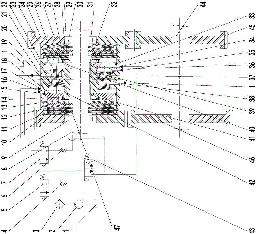
[0041] Such as figure 1 , 2 As shown, a power uninterrupted shifting device includes a fuel tank 1, an oil pump 2, a filter 3, a first electromagnetic reversing valve 7, a second electromagnetic reversing valve 5, a third electromagnetic reversing valve 43, a first one-way Valve 6, second one-way valve 4, input shaft 8, first gear 10, first steel plate 11, first friction plate 12, first pressure plate 13, first piston return spring 14, first piston return Spring seat 47, first piston inner seal ring 42, first piston outer seal ring 15, first piston oil inlet 16, first spool oil inlet 17, first piston 18, first linkage spool 23, first piston A linkage spool seal ring 19, a first linkage spool return spring 21, a first oil outlet 20, a second piston inner seal ring 40, a second piston outer sea...

Embodiment 2

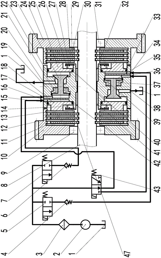
[0059] Such as image 3 As shown, in the application of electric vehicles, the input shaft 8 is connected to the output shaft of the motor, and the neutral gear can be realized by controlling the motor to stop, and there is no need for figure 2 The third solenoid selector valve 43 is shown. The first electromagnetic reversing valve 7 is connected to the first piston oil inlet 16 after connecting the first one-way valve 6, and the first spool oil inlet 17 is connected to the outlet of the first electromagnetic reversing valve 7; the second electromagnetic reversing valve 5 is connected to the second piston oil inlet 34 after being connected to the second one-way valve 4, and the second valve core oil inlet 36 is connected to the outlet of the second electromagnetic reversing valve 5. The first oil outlet 20 and the second oil outlet 38 are directly connected to the oil tank 1 . The first electromagnetic reversing valve 7 and the second electromagnetic reversing valve 5 are n...

Embodiment 3

[0062] Such as Figure 4 As shown, a power uninterrupted shifting device based on a planetary mechanism; the gearbox case 9 is fixed to the vehicle frame, and the case 9 is connected to the input shaft 32 through a bearing 8 . The first steel plate 10 is connected with the hydraulic cylinder 24 , and the first friction plate 11 is connected with the box body 9 . The second steel plate 26 is installed on the hydraulic cylinder 24, which is also the ring gear of the planetary mechanism. The second friction plate 25 is installed on the sun gear 28 of the planetary mechanism, and the sun gear 28 and the input shaft 32 are fixed. The planetary gear 27 is installed on the planetary carrier 29 through the planetary gear bearing, and the planetary carrier 29 provides power output. The structure of other components is basically the same as in Embodiment 1.

[0063] The number of teeth of sun gear 28 is z 1 , the number of teeth of the ring gear on the hydraulic cylinder 24 is z 2 ,...


PUM


Abstract

The invention discloses a power-uninterrupted hydraulic gear shifting device. A hydraulic cylinder is installed on an input shaft and is provided with two valve element cavities in which a first linkage valve element and a second linkage valve element are installed correspondingly; one side of the first linkage valve element and one side of the second linkage valve element are each of a piston structure, are sealed through linkage valve element sealing rings and are provided with linkage valve element returning springs; the other side of the first linkage valve element and the other side of the second linkage valve element are each of a conical face structure; the end face area of the conical face side of each of the first linkage valve element and the second linkage valve element is smaller than the end face area of the other end; and the first linkage valve element and the second linkage valve element are reversely installed. The power-uninterrupted hydraulic gear shifting device is used for automobile gear position switching, and in the gear shifting process, power un-interruption can be achieved; after a gear position is shifted in, oil pressure built in the hydraulic cylinder can be kept all the time; and in the gear shifting process of two gear positions, only one of the two gear positions can be shifted in, and the two gear positions are mutually locked.

Description

technical field [0001] The invention relates to a shifting device, in particular to a power uninterrupted hydraulic shifting device, in particular to a shifting device capable of realizing uninterrupted power and interlocking gear positions. Background technique [0002] The overall trend of automobile transmission system is from manual shifting to automatic shifting. In recent years, the rapid development of computer technology is applied to automobile transmission system, which makes the automatic transmission technology develop rapidly. In the application of electric vehicles, since the drive motor itself has a certain speed and torque adjustment capability, considering the cost performance, the use of two-speed to three-speed transmission can meet the use requirements. The shifting process of the traditional mechanical automatic transmission needs to go through the process of removing, selecting and engaging. Therefore, problems such as torque interruption, large mechani...

Claims


Application Information

Patent Timeline
IPC IPC(8): F16H59/02F16H61/02F16H61/4008F16H61/4061F16H61/4069
CPCF16H59/02F16H61/02F16H61/0267F16H61/4008F16H61/4061F16H61/4069
Inventor 罗玉涛
Owner SOUTH CHINA UNIV OF TECH
Why Eureka
Try Eureka