
Heat pipe radiator with oblique heat-conducting surface

A technology of heat pipe radiator and heat conduction surface, which can be used in indirect heat exchangers, lighting and heating equipment, etc., and can solve the problems of low efficiency

Inactive Publication Date: 2017-05-24
廖忠民
View PDF7 Cites 1 Cited by
  • Summary
  • Abstract
  • Description
  • Claims
  • Application Information

AI Technical Summary

Problems solved by technology

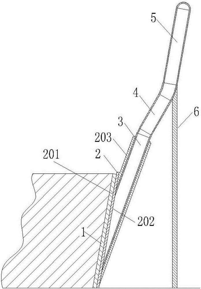
[0002] Heat pipes using the principle of phase change and heat conduction are widely used in radiator technology due to their high heat transfer efficiency; one of them uses surface contact to dissipate heat, but the existing surface contact heat pipe radiators have a general heat transfer surface in the evaporation section. It is required to be placed horizontally and lower than the heat dissipation surface of the condensation end. However, in engineering practice, it is often encountered that the heat dissipation surface is a slope with a large inclination to the horizontal plane and the heat pipe can only be in contact with one side of the work object, especially the angle between the slope and the horizontal plane> 45 °, if it is not handled properly, the efficiency is often not high, especially for radiators with non-planar curved surfaces or gravity heat pipes

Method used


Image

  • Heat pipe radiator with oblique heat-conducting surface
  • Heat pipe radiator with oblique heat-conducting surface
  • Heat pipe radiator with oblique heat-conducting surface

Examples


Embodiment 1

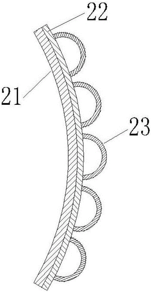
[0028] Example 1, Figure 11 It is a schematic diagram of embodiment 1, and the drawing surface is a sectional view, and the sectional plane is a vertical plane passing through the center line of the container 40 and parallel to the page; the working condition is; the inside of the container 40 needs to dissipate heat, and the heat dissipation part is carried out on the side of the conical surface of the container Heat dissipation; now adopt the heat pipe radiator on the inclined plane heat conduction surface, and the heat pipe radiator assembly 20 in the figure is to include figure 2 The combination of all parts except the heat pipe assembly, (thus, except as required in the text of this paragraph, figure 2 The parts in the Figure 11 No longer marked in), the heat pipe assembly adopts cross-section such as Figure 5The heat pipe assembly of the shown single heat pipe double-sided conformable slope heat-conducting surface heat pipe radiator; the heat-dissipating surface 4...

Embodiment 2

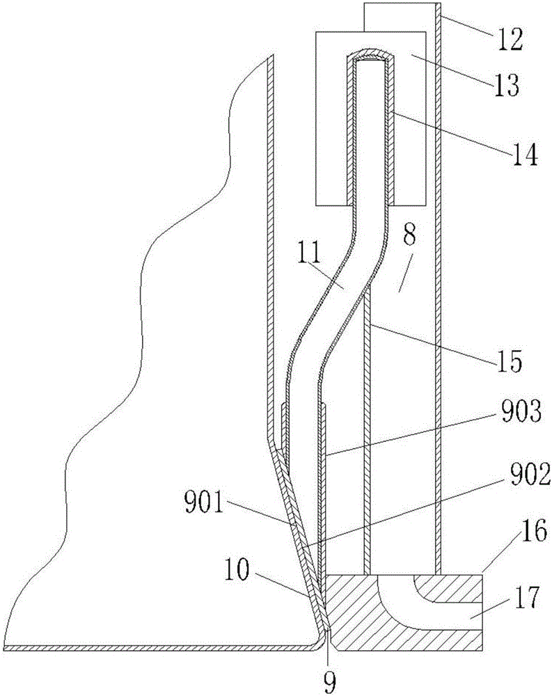
[0029] Example 2, Figure 12 It is a schematic diagram of embodiment 2, and the drawing is a sectional view, and the sectional plane is a vertical plane passing through the center line of the heat pipe and parallel to the page; Figure 12 The equipment cabinet 50 in the work is in relatively bad environment, so shell 54 adopts fully enclosed structure to strengthen protection; , the heat dissipation surface is an inclined plane, so the heat pipe radiator with an inclined plane heat conduction surface is used, and the heat pipe 18 is the same as figure 1 Combination of all parts except work object 1 and strut 6 or figure 2 The middle heat pipe 11 is similar to the heat pipe, wherein the area of ​​the heat conduction surface of the heat conduction block 43 of the evaporating section in the contact direction with the working object is ≥ the area of ​​the heat dissipation surface 42 of the heating element, and the entire area is kept in close contact, and the contact surface is ...

Embodiment 3

[0030] Example 3, Figure 13 It is a schematic diagram of embodiment 3, and the drawing is a sectional view, and the sectional plane is a vertical plane passing through the center line of the container 60 and parallel to the page; the working condition is that the inside of the container 60 needs to dissipate heat, and the heat is mainly concentrated in the lower part of the container. The heat dissipation surface 61 is an inverted cone; the heat pipe radiator on the inclined plane heat conduction surface is now used, and the heat pipe radiator assembly 67 is composed of figure 2 The combination of all parts except the heat pipe assembly, the cross section of the heat pipe assembly is as follows Figure 5 The heat pipe assembly of the shown single heat pipe double-sided conformable slope heat-conducting surface heat pipe radiator, the heat-dissipating surface 61 of the container 60 and the heat-conducting surface of the evaporation section heat-conducting block 69 of the heat...


PUM


Abstract

The invention provides a heat pipe radiator with an oblique heat-conducting surface. The heat pipe radiator with the oblique heat-conducting surface is characterized in that the included angle between the axis of an evaporation section of a heat pipe and the horizontal plane ranges from 30 degrees to 90 degrees, and the heat-conducting area is maximized on the premise that the condition is guaranteed; the included angle between the axis of a heat insulating section of the heat pipe and the horizontal plane ranges from 45 degrees to 75 degrees, and the included angle between the axis of a condensation section of the heat pipe and the horizontal plane ranges from 55 degrees to 90 degrees; an outer heat-conducting surface of a heat-conducting block of the evaporation section is kept being in close contact with the cooling surface of a working object, and auxiliary materials with good heat conductivity are smeared on the contact surface; the contact area between the inner heat-conducting surface of the heat-conducting block of the evaporation section and working media in the heat pipe is enlarged by adjusting the included angle between the inner-heat conducting surface of the heat-conducting block and the axis of the evaporation section; the condensation section of the heat pipe is inserted into a hole of a condensation section cooling rib, and condensation section cooling fins are connected with the condensation section cooling rib in a close contact mode; and a condensation section cooling assembly comprises an air cooling assembly or a liquid cooling assembly. The heat pipe radiator with the oblique heat-conducting surface has the beneficial effects that operating efficiency can be improved, energy is saved, and the environment is protected.

Description

technical field [0001] The invention relates to the field of radiators, in particular to a heat pipe radiator. Background technique [0002] Heat pipes using the principle of phase change and heat conduction are widely used in radiator technology due to their high heat transfer efficiency; one of them uses surface contact to dissipate heat, but the existing surface contact heat pipe radiators have a general heat transfer surface in the evaporation section. It is required to be placed horizontally and lower than the heat dissipation surface of the condensation end. However, in engineering practice, it is often encountered that the heat dissipation surface is a slope with a large inclination to the horizontal plane and the heat pipe can only be in contact with one side of the work object, especially the angle between the slope and the horizontal plane> 45 °, if it is not handled properly, the efficiency is often not high, especially for radiators with non-planar curved surf...

Claims


Application Information

Patent Timeline
Patent Type & Authority Applications(China)
IPC IPC(8): F28D15/02
CPCF28D15/0266
Inventor 廖忠民
Owner 廖忠民
Learn More