Air-cooled permanent magnet speed regulator

A permanent magnet governor and air-cooled technology, applied in permanent magnet clutches/brakes, electric brakes/clutches, asynchronous inductive clutches/brakes, etc., can solve the problem of large heat generation by eddy currents, inability to adjust speed, and difficulty in assembly Large and other problems, to achieve the effect of high transmission torque, good heat dissipation effect, and good heat dissipation effect

Pending Publication Date: 2017-05-24
ANHUI WOLF POWER TECH
View PDF6 Cites 8 Cited by
  • Summary
  • Abstract
  • Description
  • Claims
  • Application Information

AI Technical Summary

Problems solved by technology

[0003] 1. The eddy current generated by magnetic induction on the conductor rotor generates a huge amount of heat. When the rated power of the equipment is increased, the effect of relying on the existing fin-like heat sink to force air cooling and heat dissipation is limited, and the magnetic coupler is easily burned due to high temperature. ;
[0004] 2. The noise problem generated by the finned heat sink during the operation of the magnetic coupling is very serious;
[0005] 3. The air gap adjustment unit located in the permanent magnet rotor has complex structure, high manufacturing cost and difficult assembly;
[0006] 4. For the cam mechanism in the speed-regulating inner and outer sleeves used to form the push-pull mechanism, since the cam roller adopts a sliding contact slider in contact with the groove surface, once the lubrication of the grease is lost, it is very easy to make the slider in the groove. The slot is stuck, resulting in the inability to adjust the speed; at the same time, it cannot accurately control the axial displacement of the speed regulating mechanism, which cannot reach the required air gap size, and the speed regulation accuracy is difficult to be guaranteed
[0007] The existence of the above-mentioned main defects affects the operation stability of the entire permanent magnet governor, which not only limits the application of the permanent magnet governor in some high-power requirements occasions, but also limits the widespread application of the permanent magnet governor

Method used


Image

  • Air-cooled permanent magnet speed regulator
  • Air-cooled permanent magnet speed regulator
  • Air-cooled permanent magnet speed regulator

Examples


Embodiment Construction

[0065] The present invention will be described in further detail below in conjunction with the accompanying drawings and specific embodiments, so that those skilled in the art can more clearly understand other advantages and effects of the present invention.

[0066]It should be noted that the structures, proportions, sizes, etc. shown in the drawings of the specification are only used to cooperate with specific implementation methods, so that those skilled in the art can understand the concept of the present invention more clearly, and are not intended to limit the scope of protection of the present invention. . Any structural modification, change in proportional relationship or size adjustment should still fall within the protection scope of the present invention, provided that it does not affect the function and purpose of the present invention. For ease of description, the relative positional relationship of each component is described according to the layout of the drawin...


PUM


Abstract

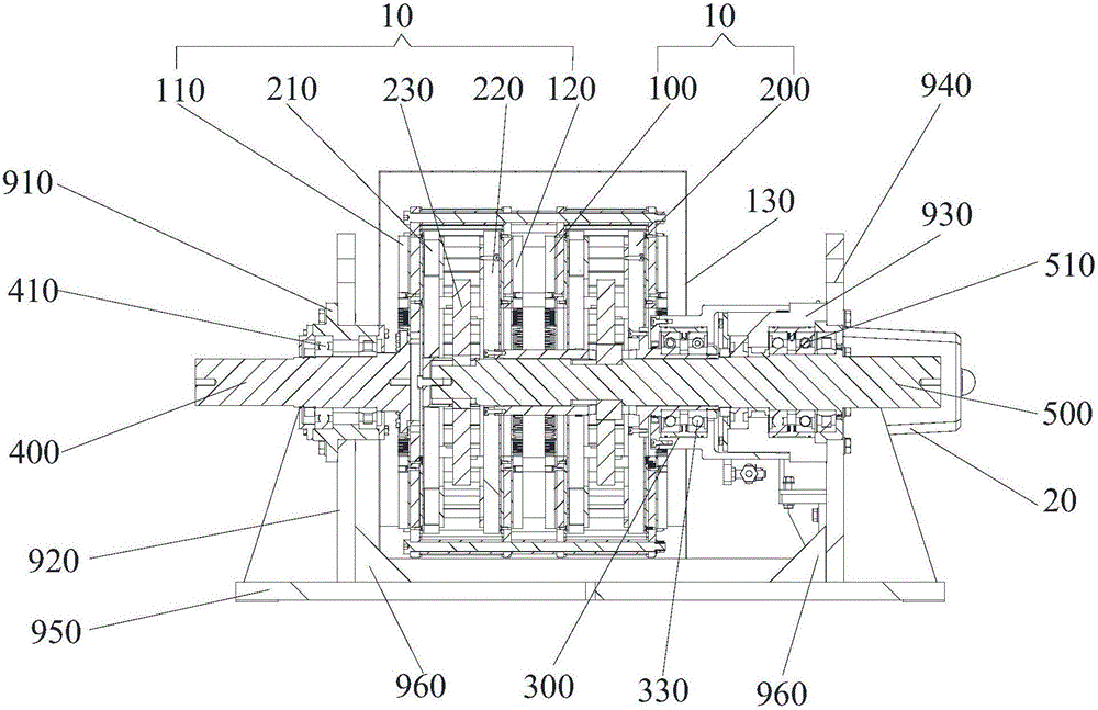
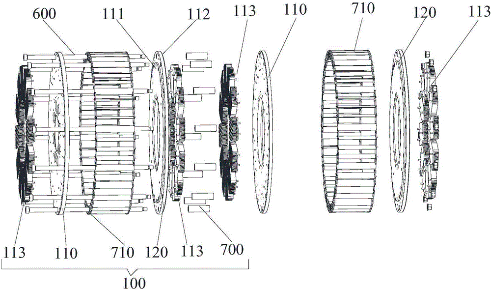
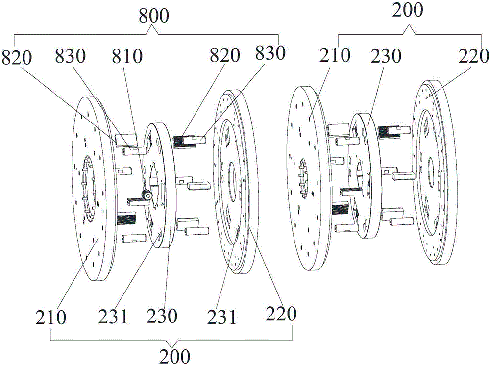
The invention discloses an air-cooled permanent magnet speed regulator, which comprises at least two rotor assemblies, wherein each rotor assembly comprises an outer rotor member, an inner rotor member and a speed regulating mechanism which is connected with the inner rotor member; the outer rotor members in the at least two rotor assemblies are serially connected in sequence by means of a serial connection member, and each inner rotor member is arranged inside the corresponding outer rotor member; each outer rotor member comprises a first outer rotor disk and a second outer rotor disk, and a first shaft is connected with the first outer rotor disk which is closest to the output end of the first shaft; each inner rotor member comprises a first inner rotor disk, a second inner rotor disk and an intermediate disk, and a second shaft connects the intermediate disks of the at least two rotor assemblies in series; and the first outer rotor disk and the first inner rotor disk are arranged in a manner of facing each other, an air gap is reserved therebetween, the second outer rotor disk and the second inner rotor disk are arranged in a manner of facing each other, and an air gap is reserved therebetween. The air-cooled permanent magnet speed regulator provided by the invention has the advantages of greater transmission torque, simple structure, convenient installation, shaft displacement prevention and easier control of air gap size.

Description

technical field [0001] The invention relates to a permanent magnet governor, in particular to an air-cooled permanent magnet governor. Background technique [0002] The Chinese Utility Model Patent Application No. 98802726.7 filed by Magnaflex Corporation of the United States discloses an adjustable magnetic coupling, which includes a first rotating shaft, a second rotating shaft, and two shafts mounted on the first rotating shaft. a conductor rotor, two permanent magnet rotors mounted on the second rotating shaft and each including a corresponding set of permanent magnets, and a push-pull mechanism, the two permanent magnet rotors are located between the two conductor rotors, and each permanent magnet rotor is connected to the two conductor rotors. There is an air gap between the opposite conductor rotors, and the two air gaps formed by the conductor rotor and the permanent magnet rotor can be increased or decreased at the same time under the action of the push-pull mechani...

Claims


Application Information

Patent Timeline
Patent Type & Authority Applications(China)
IPC IPC(8): H02K49/04H02K49/10H02K16/00
CPCH02K16/005H02K49/046H02K49/10
Inventor 余竹艳邵玉峰
Owner ANHUI WOLF POWER TECH
Why Eureka
Try Eureka