A Cross-Coupled Charge Pump

A cross-coupling and charge pump technology, applied in the direction of conversion equipment without intermediate conversion to AC, can solve the problems of large chip area occupied, low conversion efficiency of charge pump, poor robustness, etc., and achieve signal stability, simple structure, and circuit The effect of topological symmetry

Active Publication Date: 2019-10-11
SHANGHAI ADVANCED RES INST CHINESE ACADEMY OF SCI
View PDF4 Cites 0 Cited by
  • Summary
  • Abstract
  • Description
  • Claims
  • Application Information

AI Technical Summary

Problems solved by technology

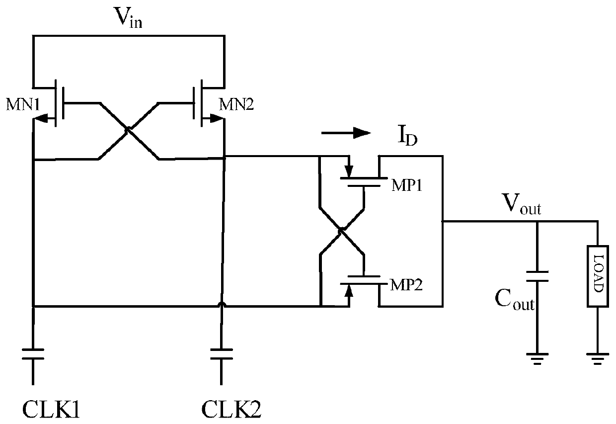
[0009] In view of the above-mentioned shortcomings of the prior art, the purpose of the present invention is to provide a cross-coupled charge pump, which is used to solve the problems of low conversion efficiency, large chip area occupation, and poor robustness of the charge pump in the prior art.

Method used


Image

  • A Cross-Coupled Charge Pump
  • A Cross-Coupled Charge Pump
  • A Cross-Coupled Charge Pump

Examples


Embodiment Construction

[0030] Embodiments of the present invention are described below through specific examples, and those skilled in the art can easily understand other advantages and effects of the present invention from the content disclosed in this specification. The present invention can also be implemented or applied through other different specific implementation modes, and various modifications or changes can be made to the details in this specification based on different viewpoints and applications without departing from the spirit of the present invention.

[0031] see figure 2 . It should be noted that the diagrams provided in this embodiment are only schematically illustrating the basic idea of ​​the present invention, and only the components related to the present invention are shown in the diagrams rather than the number, shape and shape of the components in actual implementation. Dimensional drawing, the type, quantity and proportion of each component can be changed arbitrarily dur...


PUM


Abstract

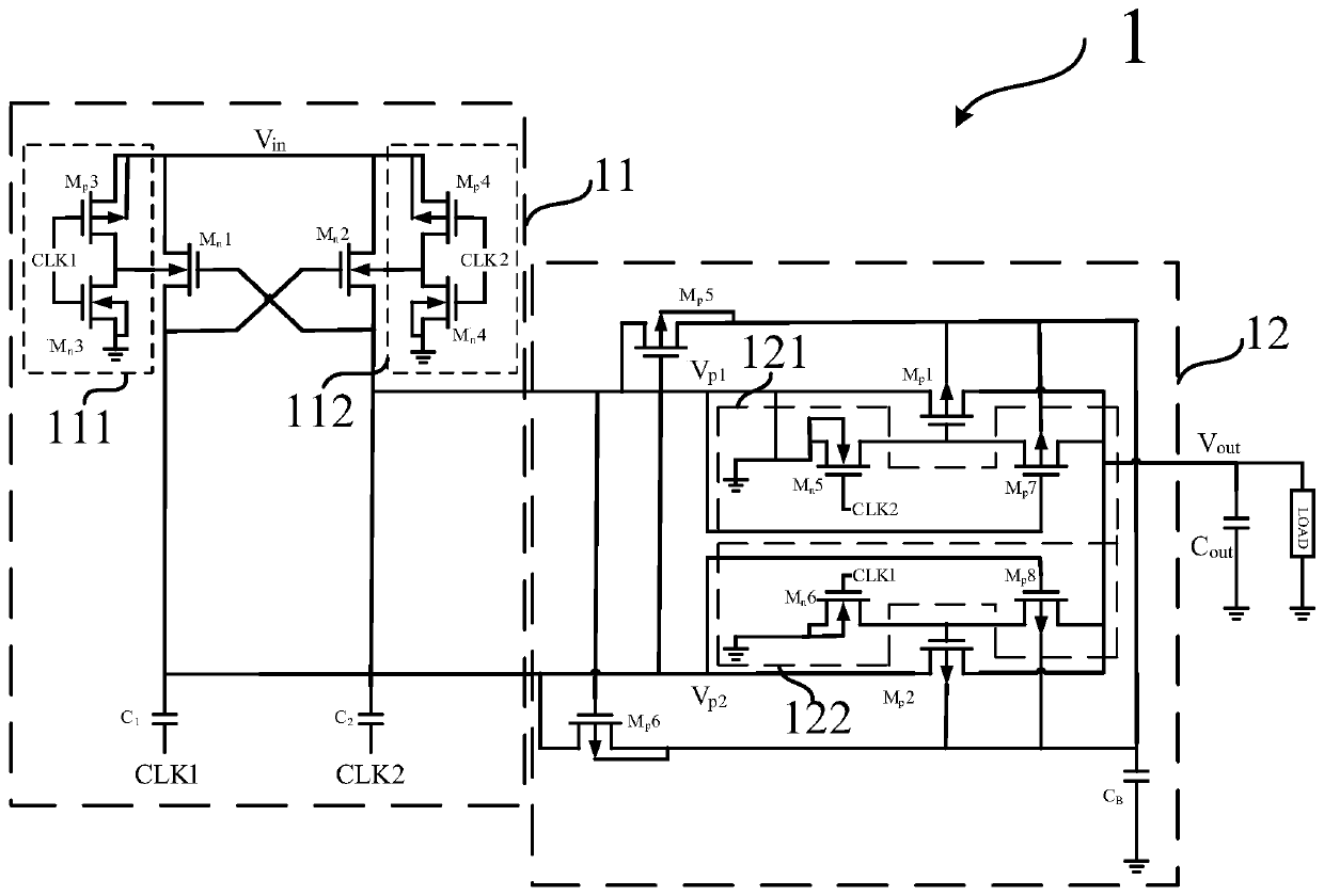
The invention provides a cross coupling charge pump comprising a boost module and a transmission module; the transmission module comprises a first transmission switch and a second transmission switch; input ends of the first and second transmission switches are respectively connected with a first output end and a second output end of the boost module; output ends of the first and second transmission switches are connected; grid ends of the first and second transmission switches are respectively connected with a first grid voltage control circuit and a second grid voltage control circuit, thus enlarging the grid voltage amplitude of the first and second transmission switches to double the power supply voltage. The cross coupling charge pump uses only two MOSFETs to enlarge the grid voltage amplitude of the PMOS transmission switches, thus using less chip areas; in addition, the substrate voltage of pair transistors can be controlled so as to reduce sub-threshold and conduction dual losses; in addition, the cross coupling charge pump is simple in structure, stable in signals, highly symmetrical in circuit topology, thus effectively reducing influences caused by nonideality factors like circuit mismatch, and providing very good robustness.

Description

technical field [0001] The invention relates to the field of power management, in particular to a cross-coupling charge pump. Background technique [0002] The main function of the driver chip of the AMOLED (Active Matrix / Organic Light Emitting Diode, active matrix organic light emitting diode panel) display panel is to receive the display and control signals in digital format transmitted by the MCU (Micro Control Unit, Micro Control Unit), and send them to the display The panel provides the gate drive voltage for row-by-row turn-on and the source drive voltage for controlling the pixel grayscale. The gate drive voltage required for small and medium-sized AMOLEDs in conventional portable devices is ±(3~8)V, and the source drive voltage is 0.3~4.2 V. These driving voltages are generated by the power management system (MPS) integrated in the driver chip. Among them, the power management system is divided into three categories according to the working mode, which are low drop...

Claims


Application Information

Patent Timeline
Patent Type & Authority Patents(China)
IPC IPC(8): H02M3/07
Inventor 汪辉田野汪宁田犁章琦封松林
Owner SHANGHAI ADVANCED RES INST CHINESE ACADEMY OF SCI
Why Eureka
Try Eureka