LED automobile lamp circuit board

A technology of LED car lights and circuit boards, applied in the field of LED lighting, can solve the problems of high junction temperature of LED chips, affecting LED luminous efficiency and service life, etc.

Inactive Publication Date: 2017-05-24
曾广文
View PDF0 Cites 0 Cited by
  • Summary
  • Abstract
  • Description
  • Claims
  • Application Information

AI Technical Summary

Problems solved by technology

[0003] The invention provides an LED car light circuit board, which solves the problem in the prior art that the junction t

Method used


Image

  • LED automobile lamp circuit board
  • LED automobile lamp circuit board

Examples


Embodiment Construction

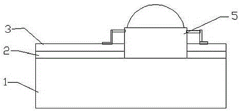
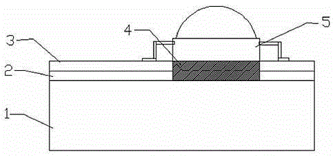
[0014] Such as figure 1 and figure 2 As shown, an LED lamp circuit board includes a heat dissipation metal substrate 1, an insulating layer 2 covering the heat dissipation substrate, a copper sheet 3 covering the insulating layer 2, and an LED chip 5 located above the copper sheet , wherein both the insulating layer 2 and the copper skin 3 are provided with holes exposing the heat dissipation metal substrate, and the bracket of the LED 5 is in direct contact with the heat dissipation metal substrate 1 through the holes of the insulation layer 2 and the copper skin 3 . On the surface of the exposed position of the heat dissipation substrate 1, that is, the surface corresponding to the holes of the insulating layer 2 and the copper skin 3, a heat conduction layer 4 is also provided. The heat conduction layer 4 can be plated with gold or silver, chromium, or zinc, or sprayed tin layer. The heat dissipation metal substrate 1 is made of copper plate, aluminum plate or other high...


PUM


Abstract

The invention discloses a LED lamp circuit board comprises a heat radiating metal substrate, an insulating layer which covers the heat radiating substrate, a copper sheet which covers the insulating layer, and an LED above the copper sheet. The copper sheet forms a printed circuit through etching, and thus the bottom of an LED chip and the heat radiating substrate are in close contact. The heat generated by the LED chip can be directly transmitted to the heat radiating metal substrate, the possibility of the gathering of the heat of the LED chip is little, the heat is radiated rapidly, thus the luminous efficiency of the LED is high, and the service life of the LED is long.

Description

technical field [0001] The invention belongs to the technical field of LED lighting, and in particular relates to an LED car light circuit board. Background technique [0002] The traditional manufacturing method of LED circuit boards for headlights of automobiles, motorcycles, and electric vehicles is to cover a high-temperature-resistant and voltage-resistant insulating layer on a heat-dissipating substrate composed of metals such as copper plates or aluminum plates with a certain thickness, and then cover the insulating layer on the insulating layer. Cover a layer of copper skin, then solder the bottom of the LED to the copper skin, and finally, solder the positive and negative electrodes of the LED to the circuit respectively. This traditional method of making the LED circuit board makes there be a gap between the bottom of the LED and the heat dissipation substrate. Insulating layer, due to the high thermal resistance and low thermal conductivity of the insulating layer...

Claims


Application Information

Patent Timeline
IPC IPC(8): H05K7/20F21S8/10
CPCH05K7/205F21S41/141F21S43/00
Inventor 王磊其他发明人请求不公开姓名
Owner 曾广文
Why Eureka
Try Eureka