Ionic polymer membrane for a carbon dioxide electrolyzer

A carbon dioxide, polymer technology, applied in the field of polymer ion exchange membrane, can solve the problem of lack of geographical storage places and so on

Active Publication Date: 2017-05-24
3M INNOVATIVE PROPERTIES CO
View PDF11 Cites 13 Cited by
  • Summary
  • Abstract
  • Description
  • Claims
  • Application Information

AI Technical Summary

Problems solved by technology

However, there are many locations where either a lack of suitable geographical storage sites or publ

Method used


Image

  • Ionic polymer membrane for a carbon dioxide electrolyzer
  • Ionic polymer membrane for a carbon dioxide electrolyzer
  • Ionic polymer membrane for a carbon dioxide electrolyzer

Examples


Embodiment approach 1

[0060] Embodiment 1. A method for the electrochemical reduction of carbon dioxide comprising:

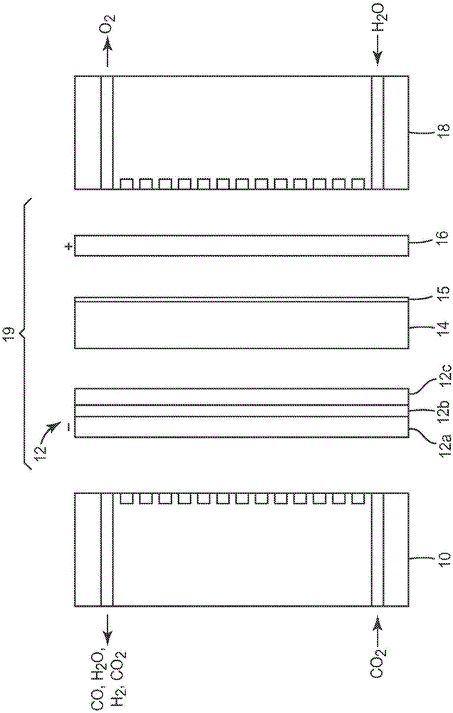
[0061] An electrochemical device is provided comprising an anode, a cathode, and a polymeric anion exchange membrane between the anode and the cathode, wherein the polymeric anion exchange membrane comprises an anion exchange polymer, wherein the anion exchange polymer comprises an anion exchange polymer selected from the group consisting of guanidinium, At least one positively charged group of a guanidinium derivative, an N-alkyl conjugated heterocyclic cation, or a combination thereof;

[0062] introducing a composition comprising carbon dioxide to the cathode; and

[0063] Electrical energy is applied to the electrochemical device to achieve electrochemical reduction of carbon dioxide.

Embodiment approach 2

[0064] Embodiment 2. The method of embodiment 1, wherein the guanidinium derivative is selected from the group consisting of thiouronium, uronium, or combinations thereof.

Embodiment approach 3

[0065] Embodiment 3. The method according to embodiment 1, wherein the N-alkyl conjugated heterocyclic cation is selected from the group consisting of N, N'-disubstituted imidazolium, 1,2,3-trisubstituted imidazolium, N- Substituted pyridiniums, N-substituted isoquinoliniums, N-disubstituted pyrrolidiniums, or combinations thereof.


PUM

PropertyMeasurementUnit
Apertureaaaaaaaaaa

Abstract

Described herein is a process for the reduction of carbon dioxide comprising: providing an electrochemical device comprising an anode, a cathode, and a polymeric anion exchange membrane therebetween, wherein the polymeric anion exchange membrane comprises an anion exchange polymer, wherein the anion exchange polymer comprises at least one positively charged group selected from a guanidinium, a guanidinium derivative, an N-alkyl conjugated heterocyclic cation, or combinations thereof; introducing a composition comprising carbon dioxide to the cathode; and applying electrical energy to the electrochemical device to effect electrochemical reduction of the carbon dioxide.

Description

technical field [0001] The invention discloses a polymer ion exchange membrane used in a carbon dioxide electrochemical device. Background technique [0002] carbon dioxide (CO 2 ) is a greenhouse gas that plays a major role in global warming and climate change. A great deal of research work has been done over the past few decades to find ways to reduce atmospheric CO 2 Emissions methodology, including carbon sinks. [0003] One of the proposed solutions is to capture CO2 at high emitting point sources such as fossil fuel based power stations, steel mills, cement plants, etc. 2 , and put CO 2 Storage or "storage" in underground depleted oil and gas fields, unrecoverable coal seams, and deep saline aquifers. However, there are many places where either a lack of suitable geographical storage sites or public opposition to local underground storage of highly compressed gases prevents this method of isolation. [0004] As an alternative, the captured CO 2 As a low-cost car...

Claims


Application Information

Patent Timeline
IPC IPC(8): C25B13/00C25B13/04C25B13/08C25B1/00C25B11/04C25B3/25C25B9/19C25B9/23
CPCC25B13/02C25B1/00C25B13/08C25B9/19C25B3/25C25B9/23C25B1/23B01J41/13C08J5/2231C08J2339/04
Inventor 泰勒·S·马修斯史蒂文·J·哈姆罗克玛丽娜·M·卡普伦克日什托夫·A·莱温斯基肖恩·M·卢奥帕
Owner 3M INNOVATIVE PROPERTIES CO
Why Eureka
Try Eureka