
Bioactive tissue fluid separating and filtering device and working method thereof

A biologically active and interstitial fluid technology, applied in separation methods, chemical instruments and methods, gravity filters, etc., can solve the problems of increased filtrate contact, large tissue residues, and long filtration time, achieving simple structural design and tissue residues The effect of small quantity and high product quality

Pending Publication Date: 2017-05-31
派生特(福州)生物科技有限公司
View PDF9 Cites 4 Cited by
  • Summary
  • Abstract
  • Description
  • Claims
  • Application Information

AI Technical Summary

Problems solved by technology

[0004] Single-stage filtration According to the purification target, install the corresponding pore size filter for one-time filtration and purification. During the filtration and purification process, due to the different sizes of particles and impurities in the interstitial fluid, it is easy to cause the filter to be clogged, resulting in the failure of effective tissue to pass through the filter completely, and a large amount of tissue residue. Cause product quality to decline, filter time is long, efficiency is low
[0005] Multiple step-by-step filtration, prepare multiple filters with different pore sizes and multiple liquid storage tanks according to needs, and filter step by step from filters with large pore sizes to filters with small pore sizes during the filtration process. The large filter filters the filtrate into the liquid storage tank before pouring the filtrate in the liquid storage tank into a filter with a small pore size for filtration, which is inconvenient to operate and many times, and increases the contact between the filtrate and the ambient air, which is easy to cause Exogenous bacterial contamination

Method used


Image

  • Bioactive tissue fluid separating and filtering device and working method thereof
  • Bioactive tissue fluid separating and filtering device and working method thereof
  • Bioactive tissue fluid separating and filtering device and working method thereof

Examples


Embodiment Construction

[0026] In order to make the above-mentioned features and advantages of the present invention more comprehensible, the following specific embodiments are described in detail with reference to the accompanying drawings.

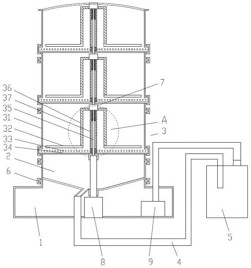
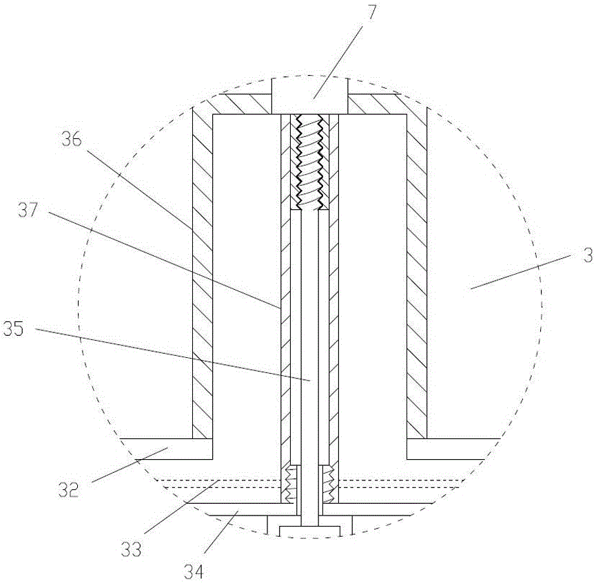
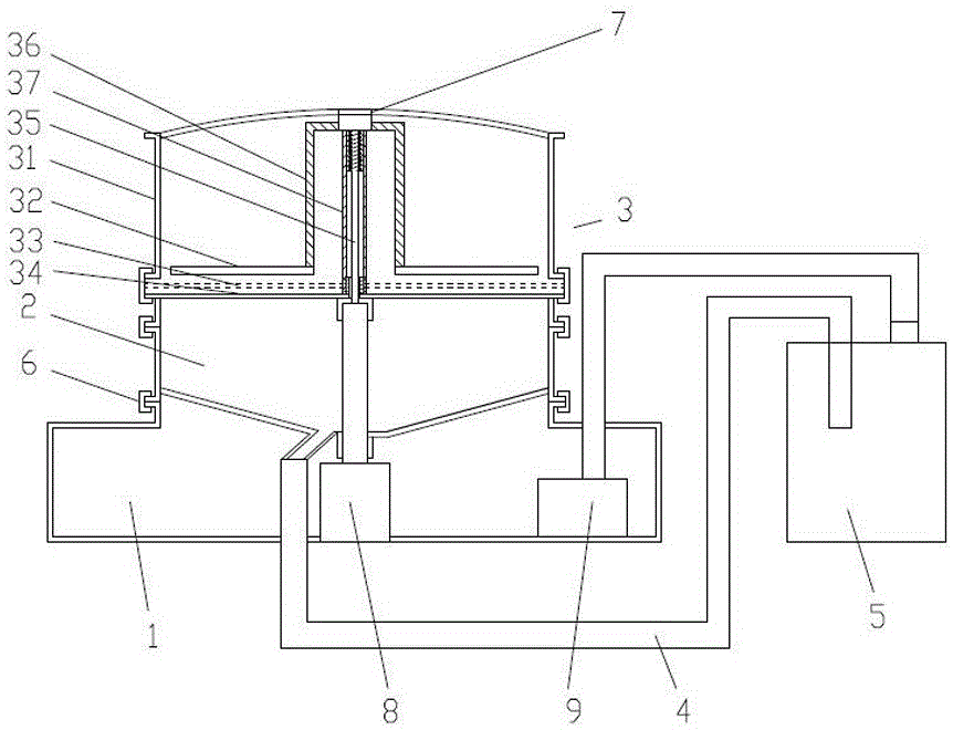
[0027] Such as Figure 1~3 As shown, a biologically active tissue fluid filter includes a base 1, a liquid receiving funnel 2 is arranged on the base 1, at least one filter assembly 3 is arranged above the liquid receiving funnel 2, and the liquid receiving funnel 2 The bottom of the filter is connected to the storage tank 5 through the pipeline 4, and the sub-filter assembly 3 includes a sub-filter cartridge 31, and the inner cavity of the sub-filter cartridge 31 is sequentially provided with a stirring paddle 32, a filter screen 33 and a porous support plate from top to bottom 34. The sub-filter cartridge 31 is pierced with a transmission rod 35 for driving the stirring paddle 32 to rotate, the filter screen 33 and the porous support plate 34 are fixed, and t...


PUM


Abstract

The invention relates to a bioactive tissue fluid separating and filtering device, which comprises a base, wherein the base is provided with a fluid bearing funnel; at least one separating and filtering assembly is arranged at the upper part of the fluid bearing funnel; the bottom of the fluid bearing funnel is connected to a storage tank through a pipe; the separating and filtering assembly comprises a separating and filtering drum; a stirring paddle, a filter net and a porous support plate are sequentially arranged in an inner cavity of the separating and filtering drum from top to bottom; and a transfer bar for driving the stirring paddle to rotate is arranged in the separating and filtering drum in a penetrating manner. The invention further relates to a working method of the bioactive tissue fluid separating and filtering device. The defects of existing single-stage filtering and multi-stage filtering are overcome; the filter net is not easily blocked, effective tissue is completely filtered, the tissue residues are few, the product quality is high, the operation is convenient and fast, and a filtered fluid is not in contact with air.

Description

technical field [0001] The invention relates to a bioactive tissue fluid subfilter and its working method. Background technique [0002] In biopharmaceutical or related experiments, it is necessary to filter the homogenized tissue fluid to remove impurities, so as to improve the purity of the produced products and improve the quality of the products. According to the requirements of biopharmaceutical GMP: in the process of product purification and filtration, aseptic operation should be performed, and it should not be contaminated by exogenous microorganisms. [0003] At present, there are mainly two methods of purification and filtration equipment, one is single-stage filtration, and the other is multiple stage-by-stage filtration. [0004] Single-stage filtration According to the purification target, install the corresponding pore size filter for one-time filtration and purification. During the filtration and purification process, due to the different sizes of particles a...

Claims


Application Information

Patent Timeline
IPC IPC(8): B01D29/085B01D29/05B01D29/56B01D29/86
CPCB01D29/05B01D29/085B01D29/56B01D29/86
Inventor 刘幼英池宗棋陈建瞿晓彬刘友霖范江钢
Owner 派生特(福州)生物科技有限公司
Learn More