
Ore crushing machine with multistage continuous crushing function

A pulverizer and secondary pulverization technology, applied in grain processing and other directions, can solve the problems of incapable of adapting to the development of energy-saving and consumption-reducing production, waste of energy and steel ball materials, abnormal wear and tear of steel balls, etc. The effect of prolonging the service life and improving the crushing efficiency

Inactive Publication Date: 2017-05-31
SICHUAN COLLEGE OF ARCHITECTURAL TECH
View PDF8 Cites 9 Cited by
  • Summary
  • Abstract
  • Description
  • Claims
  • Application Information

AI Technical Summary

Problems solved by technology

[0003] When the ball mill is working, because a lot of steel balls and materials are filled in the drum, the load of the drum rotation increases, and the power loss of the machine is relatively large; when the steel balls fall from the top of the drum, some steel balls do not hit the bottom material, but Impacting on other steel balls causes a lot of energy waste; because in many cases the collision occurs between the steel balls, the abnormal wear of the steel balls increases, resulting in a double waste of energy and steel ball materials. Therefore, Traditional ball mills have large power loss, low mechanical efficiency, and high production costs, which can no longer meet the needs of energy-saving and consumption-reducing production development.

Method used


Image

  • Ore crushing machine with multistage continuous crushing function
  • Ore crushing machine with multistage continuous crushing function

Examples


Embodiment 1

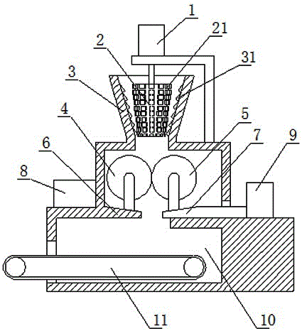
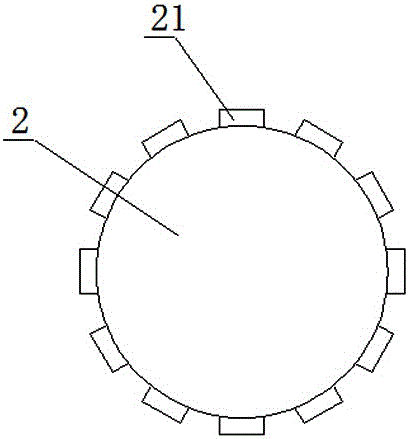
[0028] Such as figure 1 As shown, in this embodiment, an ore crusher capable of multi-stage continuous crushing is used for crushing ore, but not limited to crushing ore, including a primary crushing device, a secondary crushing device, and a secondary crushing device arranged from top to bottom in accordance with the ore flow direction. device and collection device, the primary crushing device includes an inverted conical passage 3 and a crushing roller 2 arranged in the passage 3, and the inner surface of the passage 3 is provided with several layers of A crushing teeth 31, such as figure 2 As shown, the outer surface of the crushing roller 2 is provided with several layers of B crushing teeth 21, and the crushing roller 2 is connected with the A driving device 1 through transmission. The collected ore enters the interior of the present invention from the channel 3, and the A driving device 1 is started to drive the crushing roller 2 to rotate. 21 squeeze each other so tha...

Embodiment 2

[0032] On the basis of the above embodiments, in this embodiment, the surfaces of the driving roller 4 and the driven roller 5 are provided with anti-slip stripes, so as to prevent the driving roller or the driven roller 5 from slipping with the material and affect the crushing efficiency .

Embodiment 3

[0034] On the basis of the above embodiments, in this embodiment, the B support platform 7 is slidably arranged above the collection device, and the B support platform 7 is connected to the C driving device 9 through transmission, and the C driving device 9 adopts a hydraulic cylinder. The piston rod of the hydraulic cylinder is in transmission connection with the B support platform 7 . In this way, the distance between the driving roller and the driven roller can be adjusted, which is conducive to convenient adjustment according to the particle size of the required material, thereby helping to save the use cost of the equipment.


PUM


Abstract

The invention discloses an ore crushing machine with a multistage continuous crushing function. The ore crushing machine comprises a first-stage crushing device, a second-stage crushing device and a collecting device which are sequentially arranged from up to bottom according to the ore flowing direction. The first-stage crushing device comprises an inverted conical channel and a crushing roller arranged in the channel. A plurality of layers of crushing teeth A are arranged on the inner surface of the channel. A plurality of layers of crushing teeth B are arranged on the outer surface of the crushing roller. The crushing roller is in transmission connection with a driving device A. The ore crushing machine has the beneficial effects that by the adoption of the ore crushing machine, multistage crushing can be achieved, and the crushing efficiency and crushing precision are high; by arranging the channel, materials can be added so that the materials can be supplemented in time, thus, the continuous machining function is achieved, and the crushing efficiency is improved; and by arranging the crushing teeth A and the crushing teeth B, the contact area between the ore crushing machine and the materials can be increased, and the crushing efficiency and crushing precision of the materials are improved.

Description

technical field [0001] The invention relates to the field of pulverizers, in particular to an ore pulverizer capable of multi-stage continuous pulverization. Background technique [0002] In the metallurgical industry, a large amount of ore needs to be ground for smelting; in the building material industry, cement production needs to grind the stone and add it to the raw material. In the prior art, ores and stones are generally ground by a ball mill. The ball mill has a huge drum, and steel balls of different diameters are installed in the drum. When the ball mill is working, the granular materials are loaded into the drum, and the drum is driven to rotate. The steel balls and materials are transported from the low end of the drum to the high end during the rotation process, and fall from the high end to the bottom of the drum. When falling to the bottom, the steel balls and materials collide with each other, and the materials are ground. [0003] When the ball mill is work...

Claims


Application Information

Patent Timeline
Patent Type & Authority Applications(China)
IPC IPC(8): B02C4/10B02C4/02B02C4/30B02C4/42B02C4/32
CPCB02C4/10B02C4/02B02C4/30B02C4/32B02C4/42
Inventor 张莉
Owner SICHUAN COLLEGE OF ARCHITECTURAL TECH
Learn More