Inhomogeneous plate line electric precipitation method and assembly and electric precipitation device

A technology for dust removal components and electrostatic precipitators, applied in the field of electrostatic precipitators, can solve the problems of high energy consumption, increased investment, substandard discharge of electrostatic precipitators, etc., and achieves the effects of simple operation, increased collision probability, and simple structure

Active Publication Date: 2017-05-31
INST OF PROCESS ENG CHINESE ACAD OF SCI
View PDF8 Cites 5 Cited by
  • Summary
  • Abstract
  • Description
  • Claims
  • Application Information

AI Technical Summary

Problems solved by technology

[0007] The purpose of the present invention is to propose a non-uniform plate line electrostatic precipitator method, components and electrostatic precipitator to solve the technical problems of substandard discharge, high energy consumption and increased investment in the prior art for electric precipitator

Method used


Image

  • Inhomogeneous plate line electric precipitation method and assembly and electric precipitation device
  • Inhomogeneous plate line electric precipitation method and assembly and electric precipitation device
  • Inhomogeneous plate line electric precipitation method and assembly and electric precipitation device

Examples


Embodiment 1

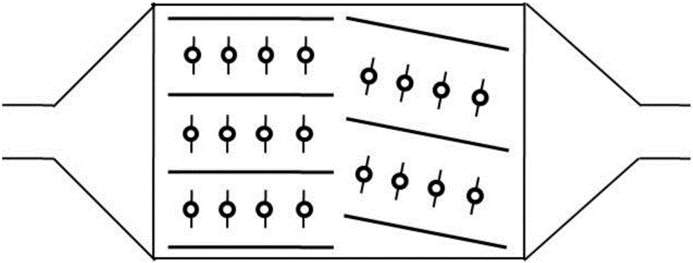
[0051] Such as figure 2 As shown, the electric precipitator has two dust removal units, and the dust removal units in the direction from the inlet 1 to the outlet 6 are the first dust removal unit, the second dust removal unit, etc., and the following embodiments are the same. The anode plate 4 of the first dust removal unit is parallel to the casing 2 (that is, the horizontal direction), the angle between the two is 0°, the angle between the anode plate 4 of the second dust removal unit and the casing 2 is 10°, and the first dust removal unit The same pole distance of the anode plate 4 is smaller than the same pole distance of the anode plate of the second dust removal unit. When the flue gas inlet flow rate is 0.8-1.2m / s, the width and length of each dust removal unit are determined according to the flue gas flow rate and residence time, and the total particulate matter is removed The efficiency exceeds 93.6%, and the removal efficiency of PM2.5 exceeds 83.1%.

Embodiment 2

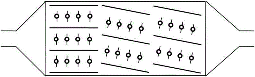
[0053] Such as image 3 As shown, the electrostatic precipitator has three dust removal units. The anode plate 4 of the first dust removal unit is parallel to the casing 2, and the angle between the two is 0°. The angle between the anode plate 4 of the second dust removal unit and the casing 2 is 20°, the angle between the anode plate 4 of the third dust removal unit and the housing 2 is still 20°, the anode plate 4 of the second dust removal unit is parallel to the anode plate 4 of the third dust removal unit, and the anode plates 4 of the three dust removal units At the same pole distance, when the flue gas inlet flow rate is 0.8-1.2m / s, the width and length of each dust removal unit are determined according to the flue gas flow rate and residence time. The total particulate matter removal efficiency is about 97.5%, and the PM2.5 removal efficiency exceeds 86.4 %.

Embodiment 3

[0055] Such as Figure 4 As shown, the electrostatic precipitator has three dust removal units, the angle between the anode plate 4 and the housing 2 of the three dust removal units is 10°, and the anode plate 4 of the first dust removal unit is parallel to the anode plate 4 of the third dust removal unit , And the direction of the included angle of the anode plate 4 of the second dust removal unit is opposite. The anode plates 4 of the three dust removal units have the same pole pitch. When the flue gas inlet flow rate is 0.8-1.2m / s, the width and length of each dust removal unit are based on the flue gas The flow rate and residence time are determined, the total particle removal efficiency is about 98.4%, and the PM2.5 removal efficiency exceeds 89.7%.


PUM


Abstract

The invention relates to the technical field of electric precipitation, in particular to an inhomogeneous plate line electric precipitation method and assembly and an electric precipitation device. The inhomogeneous plate line electric precipitation assembly comprises a plurality of sets of precipitation units arranged in sequence, each precipitation unit comprises a plurality of anode plates in parallel, and a plurality of cathode lines are arranged between adjacent anode plates; the anode plates are horizontally arranged or are arranged in an inclined manner, and the anode plates of every two adjacent precipitation units are not located on one straight line. According to the inhomogeneous plate line electric precipitation assembly, the inhomogeneous plate line electric precipitation method is adopted for arranging the anode plates and the cathode lines in all precipitation units, the anode plates are horizontally arranged or are arranged in the inclined manner, smoke turning and deflection are finally achieved, and the high purification effect is achieved. The device is simple in structure, and the purification standard can be achieved without combining other precipitation equipment.

Description

Technical field [0001] The invention relates to the technical field of electric dust removal, in particular to a non-uniform plate wire electric dust removal method and assembly and an electric dust collector. Background technique [0002] Electrostatic precipitator is a type of industrial dust removal device widely used. However, with the frequent occurrence of haze pollution, the particulate matter emission standards of various industries have become more and more stringent. The concentration of particulate matter discharged by existing electrostatic precipitators mostly exceeds 30mg / m 3 , Does not meet the emission requirements, the reason is that the diameter and quality of PM2.5 particles in the flue gas are small, and they can follow the flue gas well, and are difficult to charge and remove in the electrostatic precipitator; at the same time, the electrostatic precipitator After the accumulation of dust on the surface of the anode plate, it is easy to produce back corona and...

Claims


Application Information

Patent Timeline
Patent Type & Authority Applications(China)
IPC IPC(8): B03C3/47B03C3/34
CPCB03C3/34B03C3/47
Inventor 朱廷钰王雪
Owner INST OF PROCESS ENG CHINESE ACAD OF SCI
Why Eureka
Try Eureka