
Oil sludge recovery device

A recovery device and sludge technology, applied in material forming presses, solid separation, magnetic separation, etc., can solve the problems of rough surface of the sludge model, poor visual effect of the sludge model, etc., and achieve improved softness and plasticity, good viscosity, and difficult cracked effect

Active Publication Date: 2017-05-31
CHONGQING TENGTONG IND DESIGN
View PDF7 Cites 13 Cited by
  • Summary
  • Abstract
  • Description
  • Claims
  • Application Information

AI Technical Summary

Problems solved by technology

[0004] In order to solve the problem that the surface of the sludge model made from the sludge is easy to be rough and the visual effect of the sludge model be

Method used


Image

  • Oil sludge recovery device
  • Oil sludge recovery device
  • Oil sludge recovery device

Examples


Example Embodiment

[0018] The present invention is described in further detail below by specific embodiments:

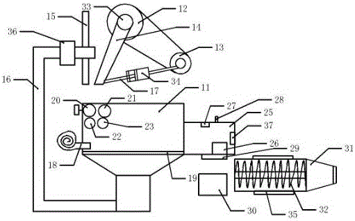
[0019] Reference numerals in the drawings in the description include:

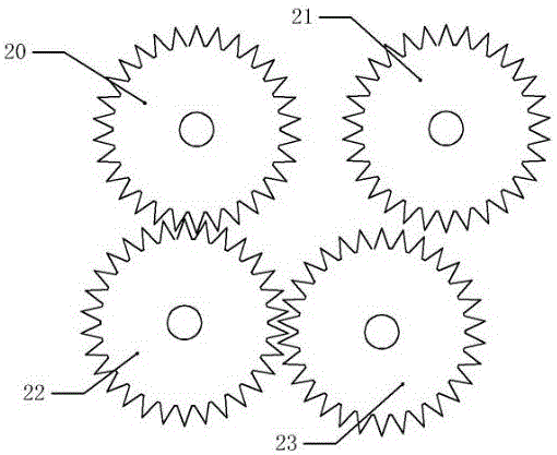
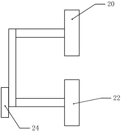
[0020] Sludge recovery bin 11, pulley 12, first motor 13, movable jaw plate 14, static jaw plate 15, return pipe 16, adjustment rod 17, blower 18, filter plate 19, first gear 20, second gear 21, The third gear 22, the fourth gear 23, the second motor 24, the trash removal box 25, the magnet block 26, the electromagnetic wave distance finder 27, the alarm device 28, the discharge door 29, the collection bag 30, the mud bin 31, the screw 32, Eccentric shaft 33 , adjustment box 34 , heater 35 , self-priming pump 36 , sprayer 37 .

[0021] like figure 1 The shown sludge recovery device includes an sludge recovery bin 11, a jaw crusher is fixedly installed above the sludge recovery bin 11, and the jaw crusher includes a pulley 12, a movable jaw plate 14 and a static jaw plate 15. The static jaw plate 15 Passing throu...


PUM


Abstract

The invention belongs to the technical field of oil sludge recovery and particularly relates to an oil sludge recovery device. An oil sludge recovery bin is fixedly provided with a jaw crusher; the oil sludge recovery bin is provided with a rolling compaction device below the jaw crusher; a sludge outlet located below the oil sludge recovery bin is a tapered opening; the large-caliber end of the tapered opening is movably provided with a filter plate; the upper layer surface of the filter plate is provided with a magnet; a plurality of filter holes are formed in the filter plate; the small-caliber end of the tapered opening is connected with a return pipe communicating with a feeding hole of the jaw crusher; the oil sludge recovery bin is fixedly provided with a blast blower; an air outlet of the blast blower is located below the rolling compaction device; the outer side of the oil sludge recovery bin is connected with an impurity removal box which is opposite to a wind gap of the blast blower and communicates with the oil sludge recovery bin; the impurity removal box is internally provided with a magnet block; and an extrusion device is arranged below the impurity removal box. The problems that the surface of an oil sludge model prepared from oil sludge is easily enabled to be rough and the visual effect of the oil sludge model is poor when waste oil sludge with scrap iron is secondarily used are solved.

Description

technical field [0001] The invention belongs to the technical field of oil sludge recovery, and in particular relates to an oil sludge recovery device. Background technique [0002] Today, with the increasing development of market economy and technology, the level of automobile design technology and manufacturing has been continuously improved. In order to meet the new requirements of the market for automobiles, automobile design also breaks through the traditional procedures, and enters a new era of independent development, adapting to the target market and improving design efficiency. The car's styling curve is extremely important, and the production and measurement of the model are the key links. The production of the scaled clay model is a crucial step in the design frontier. Its purpose is to reproduce the idea of ​​the styling design and verify the styling design The three-dimensional effects of the renderings can be optimized and demonstrated separately, and can also...

Claims


Application Information

Patent Timeline
IPC IPC(8): B09B3/00B09B5/00B02C1/04B02C4/04B02C4/08B02C23/18B03C1/02B30B11/24
CPCB02C1/04B02C4/04B02C4/08B02C23/18B03C1/02B09B3/00B09B5/00B30B11/24
Inventor 李庸健
Owner CHONGQING TENGTONG IND DESIGN
Learn More