Detecting and straightening machine and method for shaft parts

A technology of shaft parts and straightening machines, which is applied in the field of straightening machines, can solve problems such as energy consumption, low efficiency, and large position errors, and achieve the effect of reducing measurement errors

Active Publication Date: 2017-05-31
SHANDONG UNIV
View PDF6 Cites 20 Cited by
  • Summary
  • Abstract
  • Description
  • Claims
  • Application Information

AI Technical Summary

Problems solved by technology

There are problems in this way: ①Because the detection and straightening are carried out on two devices respectively, the benchmarks cannot be accurately unified, and a large position error will inevitably occur
②The forgings are transported back and forth between the two equipments, resulting in long working hours and low efficiency

Method used


Image

  • Detecting and straightening machine and method for shaft parts
  • Detecting and straightening machine and method for shaft parts
  • Detecting and straightening machine and method for shaft parts

Examples


Example Embodiment

[0045] Example 1:

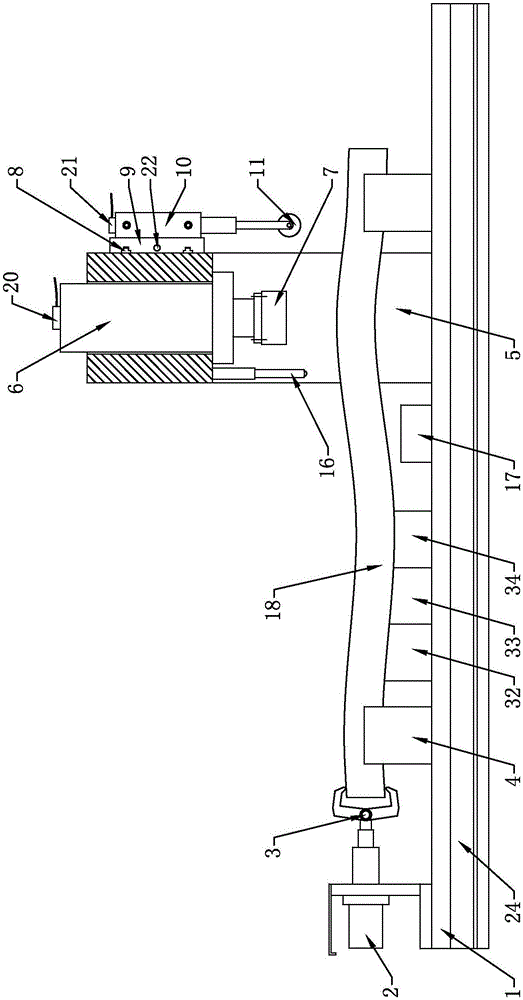
[0046] Such as figure 1 As shown, the shaft parts detection straightening machine includes a console and a straightening machine body. The console is set independently of the straightening machine body or the console is integrated into the straightening machine body.

[0047] The main body of the straightening machine includes a fixed workbench 1 and a mobile main frame 5; a first motor 2 is provided at one end of the fixed workbench 1, and the first motor 2 is a servo motor; There is a clamp 3 on the right. The clamp 3 is connected to the first motor 2 through a rotating mechanism. The first motor 2 can provide power for the rotation of the clamp 3 in its axial direction; the fixed workbench on the right side of the clamp 3 1 is provided with a support block 4 on the front and rear sides; on the front and rear sides of the fixed workbench 1 are provided with first slide grooves 24 along the length of the fixed workbench 1, and the movable main frame 5 is provid...

Example Embodiment

[0071] Example 2:

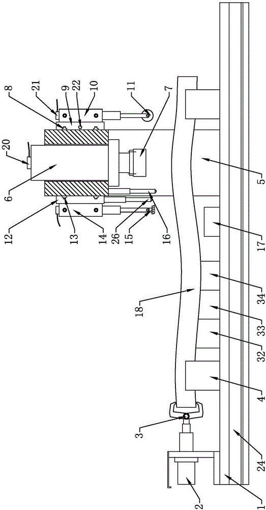
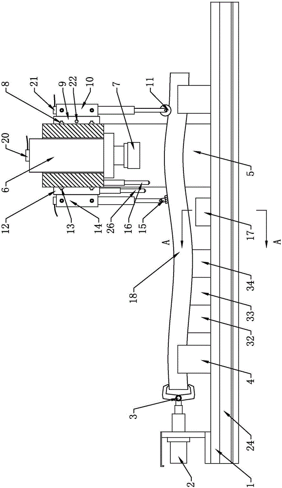
[0072] Such as Figure 2-Figure 7 As shown in the figure, the shaft parts detection straightening machine includes a console and a straightening machine body. The console is set independently of the straightening machine body or the console is integrated into the straightening machine body.

[0073] The main body of the straightening machine includes a fixed workbench 1 and a mobile main frame 5; a first motor 2 is provided at one end of the fixed workbench 1, and the first motor 2 is a servo motor; There is a clamp 3 on the right side. The clamp 3 is connected to the first motor 2 through a rotating mechanism. The first motor 2 can provide power for the rotation of the clamp 3 in its axial direction; the fixed workbench on the right side of the clamp 3 A support block 4 is provided on the front and rear sides of the fixed workbench 1; a first slide groove 24 is provided along the length direction of the fixed workbench 1 on the rear or front and rear sides of ...


PUM


Abstract

The invention discloses a detecting and straightening machine and method for shaft parts. The detecting and straightening machine comprises a console and a straightening machine body. The straightening machine body comprises a fixed work table and a movable main machine frame. The movable main machine frame can move on the fixed work table along the X axis and can feed data back to the console. A straightening hydraulic cylinder is arranged on the movable main machine frame and can straighten a workpiece. A rear bracket capable of moving along the Y axis is arranged on the rear side of the movable main machine frame. A measurement hydraulic cylinder is arranged on the rear bracket. A measurement rolling wheel is arranged below the measurement hydraulic cylinder. A displacement sensor for measuring the Y-axis movement amount and a displacement sensor for measuring the Z-axis movement amount are arranged on the movable main machine frame and the measurement hydraulic cylinder correspondingly. The displacement sensors can transmit information to the console. Detecting and straightening of the workpiece can be conducted on the same device and the same station through the same installation reference. When straightness detection is conducted on the workpiece, detection can be conducted on the workpiece on three-dimensional scale, and measurement errors are reduced.

Description

[0001] (1) Technical field [0002] The invention relates to the technical field of straightening machines, in particular to a straightening machine for detecting shaft parts and a straightening method. [0003] (2) Background technology [0004] With the rapid development of industrial technology, heavy machinery and equipment, large ships, generators (including steam turbines, wind generators, nuclear power), military products, etc. are increasingly demanding high-quality large shaft forgings. The meaning of high-quality forgings includes: ①high material mechanical properties ②high size and shape accuracy. This means that while ensuring the mechanical properties of the material, the amount of material processing must be reduced to save resources, save costs, and reduce energy consumption. [0005] Large shaft forgings are mostly obtained by hot forging. After hot forging, the material is tested at high temperature → straightened → re-tested → re-straightened until the straightness r...

Claims


Application Information

Patent Timeline
IPC IPC(8): B21D3/14B21C51/00B24B27/033B24B55/06
CPCB21C51/00B21D3/14B24B27/033B24B55/06
Inventor 刘延俊吴瀚崚薛钢杨晓玮贺彤彤刘梦超
Owner SHANDONG UNIV
Why Eureka
Try Eureka