Piezoelectric type integrated spray head used for electrofluid jet printing

A piezoelectric and electrofluidic technology, which is applied in printing and other directions, can solve problems affecting positioning accuracy, unsatisfactory spraying, uneven electric field, etc., achieve fine printing effects, improve centering performance, and improve positioning.

Active Publication Date: 2017-05-31
HUAZHONG UNIV OF SCI & TECH
View PDF7 Cites 15 Cited by
  • Summary
  • Abstract
  • Description
  • Claims
  • Application Information

AI Technical Summary

Problems solved by technology

[0005] One is that AC voltage is required to achieve on-demand printing, and it takes a certain amount of time for the AC voltage to rise from zero voltage to the set value, and it takes a certain amount of time to stabilize, which limits the frequency of AC voltage that can be used for on-demand printing. Makes on-demand printing unable to achieve high-resolution printing at high frequencies
[0006] Second, electrojet printing sprays charged droplets from the nozzle, which are small in size and are easily disturbed by the external electric field during the flight from the nozzle to the substrate, thus affecting the positioning accuracy.
However, when a voltage is applied on a curved surface, the electric field is uneven and uncontrollable
Therefore, the existing electrojet printing equipment cannot meet the requirements of spraying on curved surfaces or other complex-shaped substrates.

Method used


Image

  • Piezoelectric type integrated spray head used for electrofluid jet printing
  • Piezoelectric type integrated spray head used for electrofluid jet printing
  • Piezoelectric type integrated spray head used for electrofluid jet printing

Examples


specific Embodiment

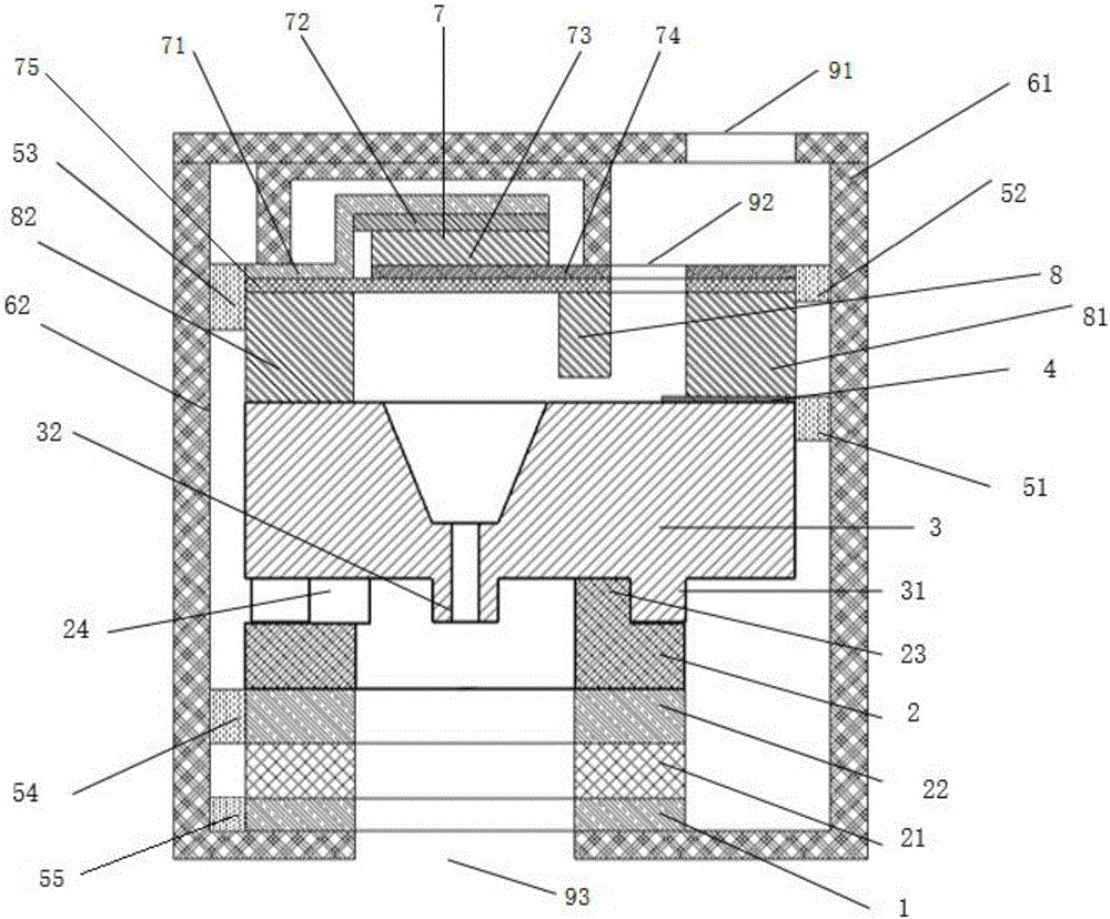
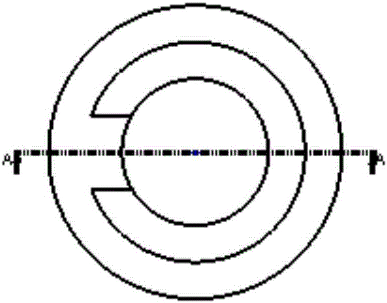
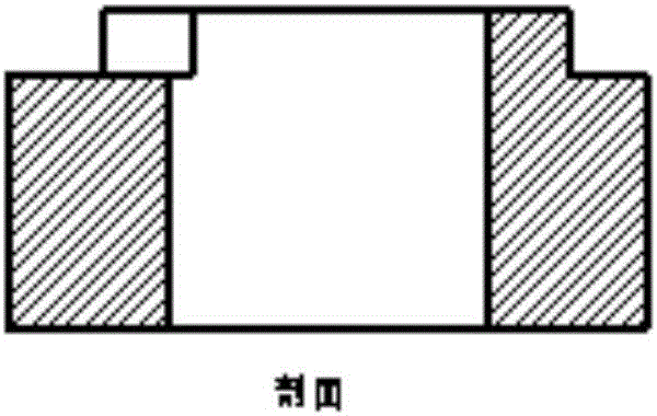
[0051] see figure 1 , a piezoelectric integrated nozzle for electrofluid jet printing, consisting of a piezoelectric structure 7, a nozzle 3, a lower electrode support ring 2 and a lower electrode ring 1. Referring to Figure 3 (a) and Figure 3 (b), the nozzle 3 is made of silicon dioxide using an etching process, and the upper part of the nozzle 3 is made into a funnel shape, which facilitates the circulation of the solution and can reduce the flow of the solution when it flows into the nozzle. 32 o'clock generation of bubbles. Bubbles will have a fatal impact on the printing process, causing the jet flow to be unstable or the solution to be sprayed out, so bubbles in the solution should be avoided as much as possible. The inner diameter of the nozzle 32 depends on the process, and the wall thickness of the nozzle 32 should be greater than 35um. On the one hand, it facilitates the nozzle processing, and on the other hand, it provides the stability of the nozzle 15. The heigh...


PUM


Abstract

The invention relates to the field of electrofluid jet printing equipment, in particular to a piezoelectric type integrated spray head used for electrofluid jet printing. The piezoelectric type integrated spray head comprises an outer bracket, a piezoelectric structure, a spray head, a lower electrode supporting ring and a lower electrode ring, wherein the piezoelectric structure is positioned above the spray head; an upper electrode is arranged on the upper part of the spray head; the lower electrode supporting ring and the lower electrode ring are sequentially arranged below the spray head; after the piezoelectric structure, the upper electrode and a lower electrode are electrified, electric fields are formed between the spray head and the lower electrode ring, so that a solution forms Taylor cones on the spray head. The piezoelectric type integrated spray head overcomes the defect that existing electric jet printing equipment cannot meet high-frequency spraying, can realize high-frequency high-resolution printing; and the lower electrode is integrated to the spray head end, so that the whole jet printing system is more flexible, and a base plate with a complex shape can be used to print. The piezoelectric type integrated spray head further has the advantages of being simple in structure, low in manufacturing cost, suitable for large-scale production and the like.

Description

technical field [0001] The invention relates to the field of electrohydrodynamic jet printing equipment, in particular to a piezoelectric integrated nozzle for electrofluid jet printing, which can realize high-frequency, high-resolution printing, and is suitable for printing substrates of different shapes such as curved surfaces . Background technique [0002] Electrohydrodynamic jet printing is to apply a high voltage between the nozzle and the substrate to form a strong electric field to pull the solution out of the nozzle, which can form dot spray, spray and spinning processes. Electrohydrodynamic jet printing is jetted through a Taylor cone, whose geometric size is much smaller than the size of the nozzle, so it can achieve higher resolution than traditional inkjet printing. [0003] Electrohydrodynamic jet printing currently has two working modes, one is to apply high pressure between the nozzle and the substrate to form continuous jet printing, and the other is to app...

Claims


Application Information

Patent Timeline
Patent Type & Authority Applications(China)
IPC IPC(8): B41J2/14
CPCB41J2/14201
Inventor 黄永安钟瑞刘宇吴学洲
Owner HUAZHONG UNIV OF SCI & TECH
Why Eureka
Try Eureka