wine storage tank
A technology for storing wine and tanks, which is applied in the field of wine storage tanks, and can solve the problems affecting beer's killing power, carbon dioxide loss, and easy escape of carbon dioxide, so as to achieve good cooling and fresh-keeping effects, improve the killing power, and avoid a large amount of loss Effect
- Summary
- Abstract
- Description
- Claims
- Application Information
AI Technical Summary
Problems solved by technology
Method used
Image
Examples
Embodiment 1
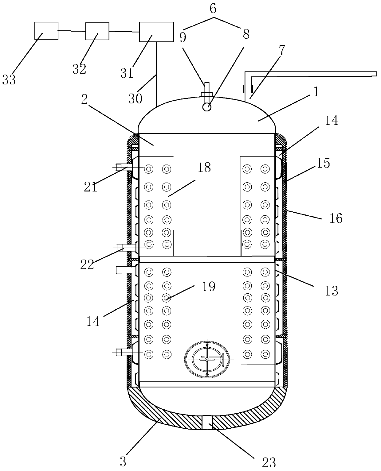
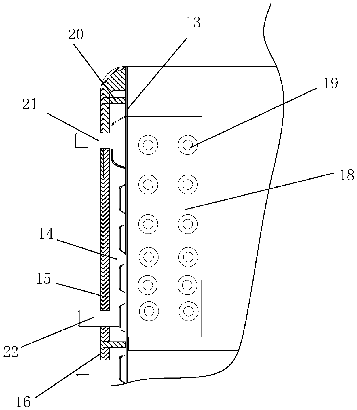
[0033] Example 1 as figure 1 with figure 2 As shown, the wine storage tank includes a tank top 1, a tank body 2 and a tank bottom 3, and the three are connected together by welding. There are four supporting feet 4, which are respectively welded on the bottom of the tank bottom 3. An elastic pad 5 is installed on the lower end of each supporting foot 4 .
[0034] The tank top 1 is in the shape of a round arch; a safety valve, a suspension ring and a cleaning device 6 are respectively installed on the top wall. The cleaning device 6 is installed at the center of the tank top 1; the filling inlet 7 is provided on one side of the cleaning device 6 . The cleaning device 6 includes a universal cleaning head 8 and a water delivery pipe 9 provided in the tank body 2; the water delivery pipe 9 is provided with an interface through which the pressure pump is connected. Also be equipped with pressure gauge on the water delivery pipe 9.
[0035] The filling inlet 7 is connected wit...
Embodiment 2
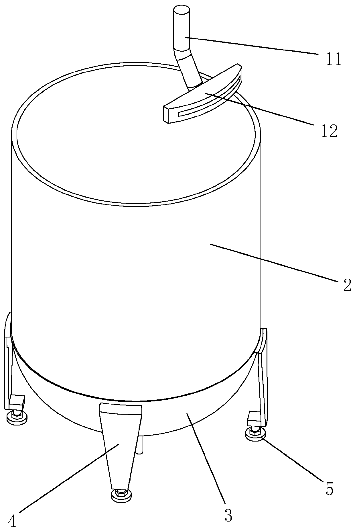
[0041] Embodiment 2 The difference between embodiment 2 and embodiment 1 is: see image 3 , inside the tank top 1, a deflector 10 is connected to the filling inlet 7. The deflector 10 includes a deflector 11 that is connected to the filling inlet 7 at one end and is inclined toward the inner wall of the tank body 2 , and a pipe head 12 that is sleeved on the other end of the deflector tube 11 and is close to or attached to the inner wall of the tank body 2 . The pipe head 12 is in the shape of a cuboid, and its water outlet end is arc-shaped, and fits with the arc of the inner wall of the tank body 2 . The beer enters from the filling inlet 7 through the pipeline, and then is output from the pipe head 12 through the draft tube 11 and flows down slowly along the inner wall of the tank body 2 .
Embodiment 3
[0042] Embodiment 3 The difference between Embodiment 3 and Embodiment 1 is: see Figure 4 The deflector 10 includes a liquid inlet pipe 24 connected to the filling inlet 7 at one end and arranged vertically downward, and a guide ring 25 connected to the liquid inlet pipe 24 and attached to the inner wall of the tank body 2 along the circumference of the tank body 2 . See Figure 5 The guide ring 25 includes a ring body 26 and a ring edge 27 extending obliquely downward along the outer edge of the ring body 26 . The ring body 26 is provided with guide grooves 28 along its radial direction. A plurality of branch channels 29 communicating with the guide groove 28 are opened on the ring edge 27 .
[0043] Beer enters the diversion groove 28 in the diversion ring 25 through the diversion pipe 11, and then flows into the branch channels 29 along the diversion groove 28;
PUM
 Abstract
Description
Claims
Application Information
 - R&D
- Intellectual Property
- Life Sciences
- Materials
- Tech Scout
- Unparalleled Data Quality
- Higher Quality Content
- 60% Fewer Hallucinations
Browse by: Latest US Patents, China's latest patents, Technical Efficacy Thesaurus, Application Domain, Technology Topic, Popular Technical Reports.
© 2025 PatSnap. All rights reserved.Legal|Privacy policy|Modern Slavery Act Transparency Statement|Sitemap|About US| Contact US: help@patsnap.com


