glass furnace

A glass furnace and glass liquid technology, applied in glass furnace equipment, glass manufacturing equipment, manufacturing tools, etc., can solve the problems of easily damaged furnace walls and refractory powder materials

Active Publication Date: 2019-11-01
DONGXU OPTOELECTRONICS TECH CO LTD
View PDF2 Cites 2 Cited by
  • Summary
  • Abstract
  • Description
  • Claims
  • Application Information

AI Technical Summary

Problems solved by technology

[0003] The purpose of the present disclosure is to provide a glass furnace to solve the problem that the powder in the glass batch is refractory and the furnace wall is easily damaged

Method used


Image

  • glass furnace
  • glass furnace
  • glass furnace

Examples


Embodiment Construction

[0027] Specific embodiments of the present disclosure will be described in detail below in conjunction with the accompanying drawings. It should be understood that the specific embodiments described here are only used to illustrate and explain the present disclosure, and are not intended to limit the present disclosure.

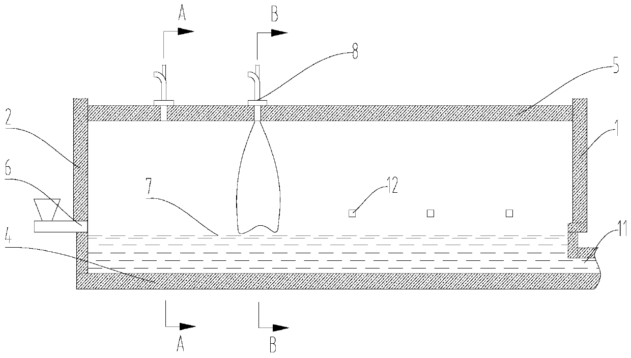
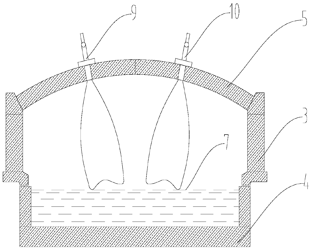
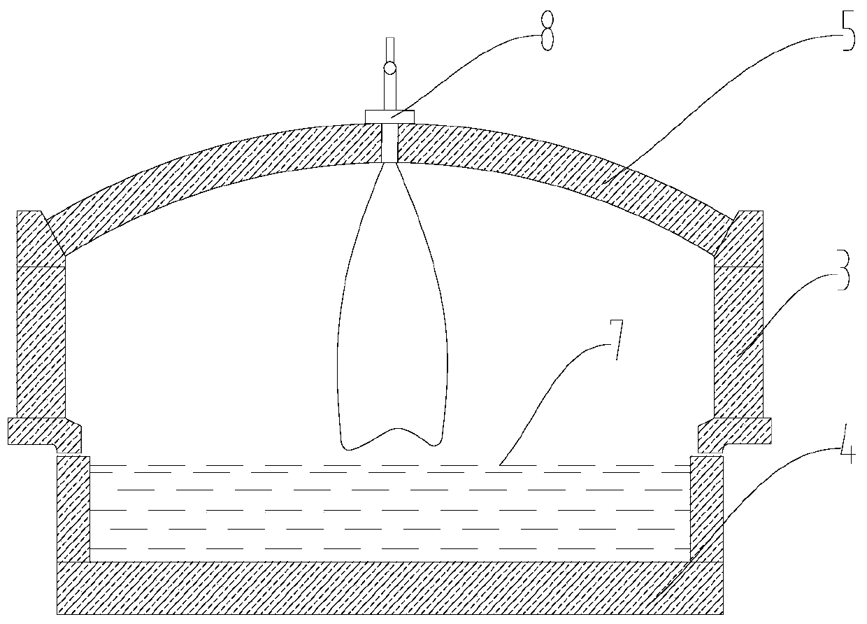
[0028] In this disclosure, unless stated otherwise, the orientation words used such as "up and down" refer to the up and down of the glass furnace when it is in use. Specifically, refer to Figure 1 to Figure 3 The direction of the drawing; "front and back" refers to the flow direction of the glass liquid, specifically, figure 1 In , the right side of the drawing is the front, and the left side is the back. In addition, the terms "first", "second", and the like used in the present disclosure are for distinguishing one element from another, and do not have sequence or importance.

[0029] Such as Figure 1 to Figure 3 As shown, the glass furnace provided by...


PUM


Abstract

The disclosure relates to a glass furnace, comprising a melting pool surrounded by a front end wall (1), a rear end wall (2), a side wall (3) and a bottom wall (4), and a slab located above the melting pool The top (5), the rear end wall (2) is provided with a material inlet (6), and one end of the roof (5) close to the material inlet (6) is provided with a device capable of facing the glass liquid surface ( 7) First combustion means for injecting flame. The first combustion device is installed in the area close to the glass liquid inlet, which directly sprays flames towards the glass liquid surface. The heat radiation of the flame and the hot smoke convection directly heat the glass liquid, which can strengthen the heat transfer and heat transfer of the glass batch materials. Radiation maximizes the heat transfer of heat to the molten glass, thereby solving the problem of some powder refractory. In addition, the burning flame of the dome directly radiates and transfers heat to the molten glass, and the flame is vertical, which can avoid burning the side wall.

Description

technical field [0001] The present disclosure relates to the field of glass manufacturing, in particular to a glass furnace. Background technique [0002] When the glass furnace melts some special glass, some powders in the glass batch are relatively difficult to melt. The melting difficulty of various batches is quite different, and it is more difficult to melt to obtain good quality glass liquid. The heat transfer in the glass kiln is manifested in the heat exchange caused by the temperature difference, while in the general horizontal flame kiln, the heat is exchanged in a direction parallel to the flow of the glass liquid in the kiln, which has the disadvantage of low heat transfer efficiency , There is also heat radiation from horizontal flame combustion to the large wall in the kiln and the kiln wall, which makes the kiln easy to be corroded, affects the safe operation of the kiln, and increases the maintenance cost of the kiln. Contents of the invention [0003] The...

Claims


Application Information

Patent Timeline
Patent Type & Authority Patents(China)
IPC IPC(8): C03B5/235
CPCC03B5/2353
Inventor 周有方王耀君
Owner DONGXU OPTOELECTRONICS TECH CO LTD
Why Eureka
Try Eureka