Leaching tank

A technology of leaching tanks and boxes, applied in the field of leaching equipment, can solve problems such as difficult maintenance, easy to be corroded, and inconvenient operation, and achieve the effects of corrosion prevention, reduced workload, and convenient maintenance

Inactive Publication Date: 2017-05-31
GUIZHOU UNIV
View PDF7 Cites 4 Cited by
  • Summary
  • Abstract
  • Description
  • Claims
  • Application Information

AI Technical Summary

Problems solved by technology

[0002] At present, the stirring motor of many leaching tanks is located at the top of the leaching tank. When adding minerals to the leaching tank, the stirring device must be removed, which is cumbersome to operate, and the leaching residue must be dumped as a whole, which is not easy to operate.
In addition, since the stirring motor is exposed to the air for a long time and is in contact with the leachate, it is easily corroded and difficult to maintain

Method used


Image

  • Leaching tank
  • Leaching tank

Examples


Embodiment Construction

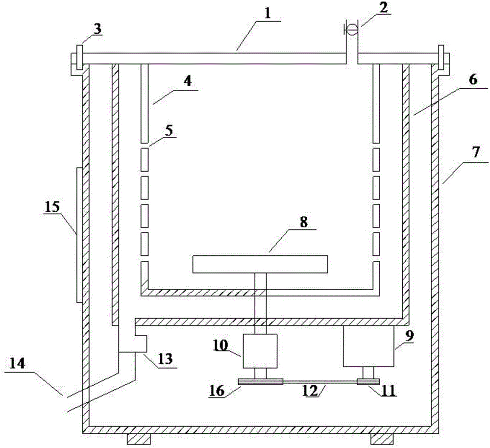
[0012] In order to make the purpose, technical solution and advantages of the present invention clearer, the present invention will be further described in detail below in conjunction with the accompanying drawings and embodiments.

[0013] Embodiment of the present invention: the structural representation of leaching tank is as figure 1 As shown, it includes a box body 7, and a leaching tank inner tank 4 and an leaching tank outer tank 6 arranged in the box body 7, and a stirring motor 9 and a deceleration clutch 10 are fixed on the bottom of the leaching tank outer tank 6 by bolts, and the stirring motor 9 The diameter of the first pulley 11 of the stirring motor 9 is less than the diameter of the second pulley 16 of the reduction clutch 10 through a belt 12 transmission connection with the reduction clutch 10; the rotating shaft of the reduction clutch 10 passes through the leaching tank inner tank 4 and outside the leaching tank The bottom of the tank 6 is connected to the...


PUM


Abstract

The invention discloses a leaching tank which comprises a box body, an inner leaching tank body and an outer leaching tank body, wherein the inner leaching tank body and the outer leaching tank body are arranged in the box body. A stirring motor and a decelerating clutch are fixed to the bottom of the outer leaching tank body through bolts. The stirring motor is in transmission connection with the decelerating clutch through a belt. A rotary shaft of the decelerating clutch penetrates through the bottom of the inner leaching tank body and the bottom of the outer leaching tank body and then is connected with an impeller inside the inner leaching tank body. Pulp discharging holes communicating with the outer leaching tank body are formed in the side wall of the inner leaching tank body. A pulp discharging electromagnetic valve is arranged at the bottom of the outer leaching tank body. The pulp discharging electromagnetic valve is connected with a pulp discharging pipe stretching out of the box body. According to the leaching tank, automatic pulp discharging can be achieved, the workload is reduced, automatic cleaning can be achieved, and maintenance is convenient. Meanwhile, the stirring motor is located at the bottom of the leaching tank and inside the box body, the contact probability between the stirring motor and pulp is decreased, and corrosion of leaching liquor to the stirring motor can be prevented.

Description

technical field [0001] The invention relates to a leaching tank, which belongs to the technical field of leaching equipment. Background technique [0002] At present, the stirring motors of many leaching tanks are located at the top of the leaching tank. When adding minerals to the leaching tank, the stirring device must be removed. In addition, since the stirring motor is exposed to the air for a long time and is in contact with the leachate, it is easily corroded and difficult to maintain. Contents of the invention [0003] The purpose of the present invention is to provide a leaching tank capable of automatic pulp discharge, convenient operation, automatic flushing, easy maintenance, practicality and simple operation, and to provide a feasible device for gold mine pulp discharge, so as to overcome the deficiencies in the prior art . [0004] A leaching tank of the present invention includes a box body, an inner tank of the leaching tank and an outer tank of the leachi...

Claims


Application Information

Patent Timeline
Patent Type & Authority Applications(China)
IPC IPC(8): C22B3/02C22B3/04C22B11/00
CPCC22B3/02C22B3/04C22B11/04Y02P10/20
Inventor 唐云马德全
Owner GUIZHOU UNIV
Why Eureka
Try Eureka