Strong shearing and stirring aluminum alloy melt composite treatment device and technology

A technology of aluminum alloy melt and compound treatment, which is applied in the field of aluminum alloy smelting, and can solve problems such as coarse crystal grains of castings, incomplete treatment of atomic hydrogen and oxide inclusions, failure to achieve high-quality wheel hub mechanical properties and appearance, etc.

Inactive Publication Date: 2017-05-31
JIANGSU KAITE AUTO PARTS
View PDF3 Cites 10 Cited by
  • Summary
  • Abstract
  • Description
  • Claims
  • Application Information

AI Technical Summary

Problems solved by technology

At present, for the treatment of aluminum melt, the industry generally adopts the method of spreading the covering agent on the surface of the melt in the transfer bag, pressing the refining agent into the aluminum solution with a bell jar, and then using nitrogen as the carrier to spray Although this method can eliminate part of the gas and oxide slag inclusions in the molten aluminum, the treatment of atomic hydrogen and oxide inclusions in the melt is not thorough, and the refining and purification effect is not ideal. The treated aluminum The general density of the melt is 2.53~2.60g / cm after hydrogen test 2 , the quality of the melt is only suitable for the production of ordinary wheels, and cannot meet the requirements of mechanical properties and appearance of high-quality wheels. The above treatment methods have limited effects on the uniform distribution of components and particles, which will cause the castings to crystallize and solidify, and the grains will be coarse; therefore, technical R&D personnel in the aluminum wheel hub industry need to develop better aluminum melt refining treatment devices

Method used


Image

  • Strong shearing and stirring aluminum alloy melt composite treatment device and technology
  • Strong shearing and stirring aluminum alloy melt composite treatment device and technology

Examples


Embodiment Construction

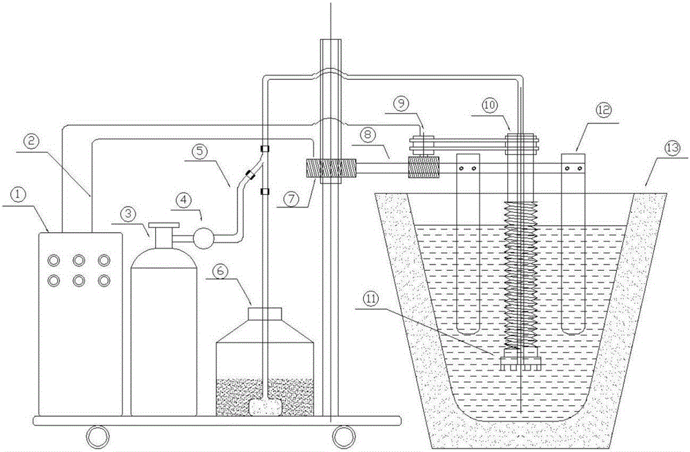
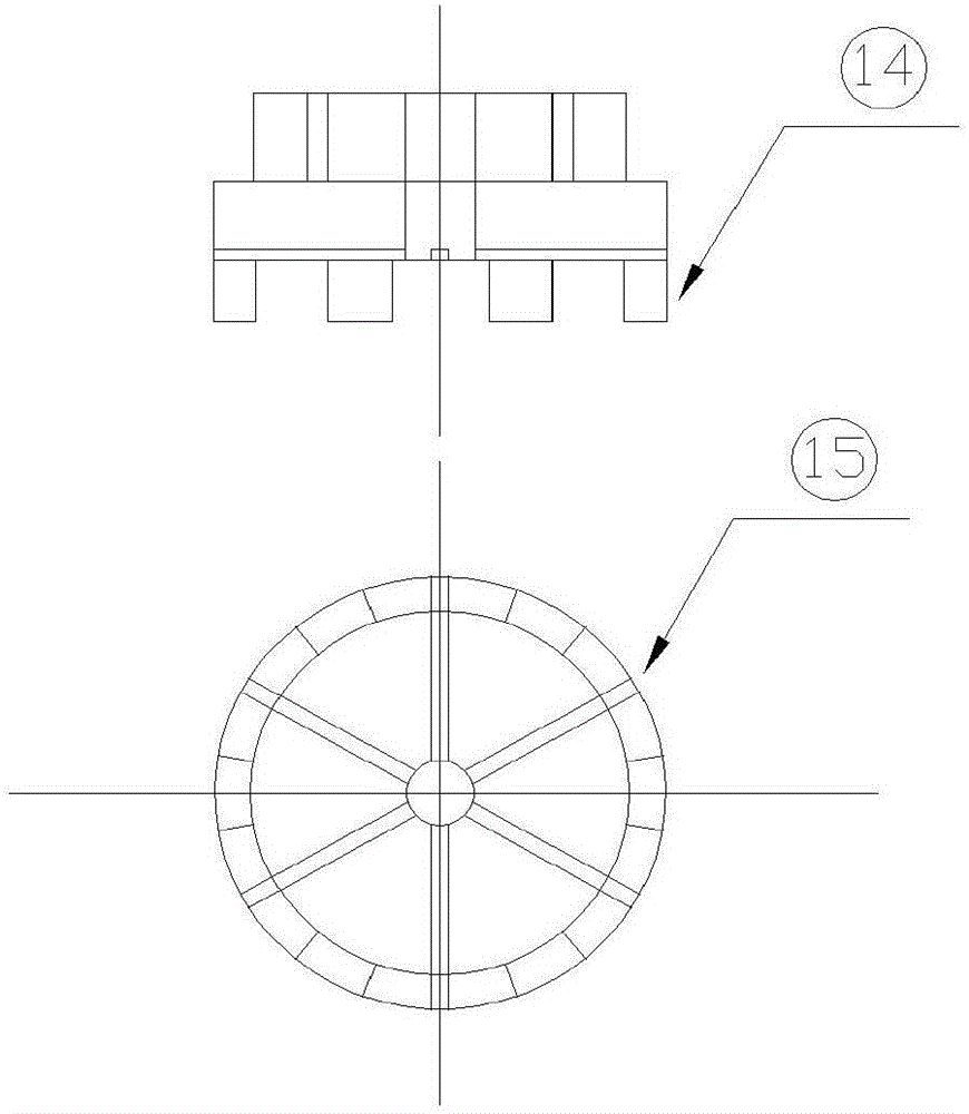
[0011] A strong shear and stirring aluminum alloy melt compound processing device, including a control cabinet 1, a wire 2, a gas storage bottle 3, a gas flow control valve 4, a gas pipe 5, a powder storage tank 6, a lifting system drive motor 7, and a support rod 8 , graphite rotor drive motor 9, graphite rotor 10, rotary nozzle 11, slag scraper 12, transfer bag 13; control cabinet 1 is connected with lifting system drive motor 7 and graphite rotor drive motor 9 through wire 2, and controls support rod 8 Up and down movement and the rotation of the graphite rotor drive motor 9; the graphite rotor drive motor 9 and the graphite rotor 10 are installed on the support rod 8, and the support rod 8 is connected with the lifting system drive motor 7; the graphite rotor drive motor 9 is connected to the graphite rotor 10 through a belt Connect and drive the graphite rotor to rotate to shear and stir the melt. There is a hole with a diameter of 10mm in the middle of the graphite rotor,...


PUM

PropertyMeasurementUnit
diameteraaaaaaaaaa
heightaaaaaaaaaa
depthaaaaaaaaaa

Abstract

The invention relates to a strong shearing and stirring aluminum alloy melt composite treatment device and technology. The device comprises a control cabinet, a wire, a gas storage bottle, a gas flow control valve, a gas pipe, a powder storage tank, a lifting system drive motor, a supporting rod, a graphite rotor drive motor, a graphite rotor, a rotary spray head, scum boards and a transfer bag. A gas flow and powder adding channel is arranged in a middle hole of the graphite rotor. Powder in the powder storage tank is a refining agent and a grain refiner. The part, immersed in melt, of the graphite rotor is in a left screw type thread type. The scum boards are arranged on the two sides of the graphite rotor. An Al-Sr-RE intermediate alloy is added and preheated into the kermesinus transfer bag, 1.0 kg to 1.5 kg of a dry covering agent is uniformly spread on the surface, 1.0 kg to 1.5 kg of the dry refining agent and 1.0 kg to 1.5 kg of the dry grain refiner are added into a powder storage bottle, the graphite rotor is moved to the position 80-100 mm away from the bottom of the transfer bag, and refining and purifying are started. The device and technology have the better effects of degassing purification, refining and homogenization.

Description

technical field [0001] The invention relates to the field of aluminum alloy smelting, in particular to a strong shear stirring aluminum alloy melt composite processing device and technology. Background technique [0002] In recent years, the rapid development of the global auto industry, especially the Chinese auto industry, has driven the development of the auto parts manufacturing industry, and the aluminum alloy wheels, which are key auto parts, have also ushered in a period of rapid growth. According to the statistics of China Wheel Association, in 2015, the export of aluminum alloy wheels in mainland China reached 75 million pieces, with a value of 3.867 billion US dollars and an export volume of 788,600 tons. China has become the world's largest manufacturer and exporter of aluminum wheels. [0003] The manufacture of aluminum wheels involves multiple links such as molten aluminum melting, casting, heat treatment, machining, and surface treatment. Among them, melt trea...

Claims


Application Information

Patent Timeline
Patent Type & Authority Applications(China)
IPC IPC(8): C22C1/02C22C1/06
CPCC22C1/026C22C1/06
Inventor 李萍胡因行孔祥建
Owner JIANGSU KAITE AUTO PARTS
Why Eureka
Try Eureka