Tensioning mechanism for anode steel claw
The technology of tensioning mechanism and anode steel claw is applied in the field of anode steel claw accessories, which can solve the problems of inconvenient use, large modification of anode carbon block and steel claw structure, etc., so as to reduce workload, improve electrical conductivity, and reduce transformation cost. Effect
- Summary
- Abstract
- Description
- Claims
- Application Information
AI Technical Summary
Problems solved by technology
Method used
Image

Examples
Embodiment 1
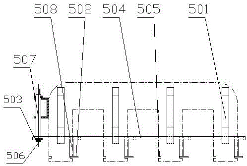
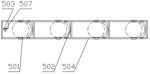
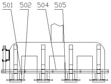
[0018] Example 1. Such as Figure 1-3 As shown, the anode steel claw tensioning mechanism includes a clip 501 connected to the steel claw. The clip 501 is provided with a fastening block 502 inserted into the carbon bowl. The clip 501 is connected to a bracket 504 for moving the fastening block 502 . The stroke of the fastening block 502 in the charcoal bowl is moved by the bracket 504 to complete the function of fixing the charcoal block.
[0019] A mounting groove 505 is made in the steel claw, and the clip 501 and the fastening block 502 are placed in the mounting groove 505 in the steel claw. The fastening block 502 is made into an arc shape, and the contact surface with the charcoal bowl is larger and more stable.
[0020] The bracket 504 is connected to the rotating rod 507, and the connecting parts of the bracket 504 and the rotating rod 507 are respectively provided with a toothed belt 503 and a toothed end 506 for engagement. . The sliding rod 508 is fixedly conne...
Embodiment 2
[0022] Example 2. Anodized steel jaw tensioning mechanism such as Figure 4-5 As shown, it includes a clamp 501 connected to the steel claw. The clamp 501 is provided with a fastening block 502 inserted into the charcoal bowl. The clamp 501 is connected with a bracket 504 for moving the fastening block 502. The clamp 501 is for rotating Shaft, the upper part of the rotating shaft is connected with the steel claw, and can rotate around the connection position, the lower part of the rotating shaft is connected to the upper end of the bracket 504, and the lower end of the bracket 504 is provided with a fastening block 502. The bracket 504 and the fastening block 502 are arranged in the installation groove 505 of the steel claw.
[0023] When in use, process an annular groove in the carbon bowl of the anode carbon block, and drive the bracket 504 through the rotation of the rotating shaft of the clamp 501, insert the fastening block 502 into the annular groove, pour aluminum wate...
PUM
 Abstract
Description
Claims
Application Information
 - R&D
- Intellectual Property
- Life Sciences
- Materials
- Tech Scout
- Unparalleled Data Quality
- Higher Quality Content
- 60% Fewer Hallucinations
Browse by: Latest US Patents, China's latest patents, Technical Efficacy Thesaurus, Application Domain, Technology Topic, Popular Technical Reports.
© 2025 PatSnap. All rights reserved.Legal|Privacy policy|Modern Slavery Act Transparency Statement|Sitemap|About US| Contact US: help@patsnap.com