Long needle valve hole plate type electronic control oil atomizer without static leakage

An electronically controlled fuel injection and fuel injector technology, which is applied to machines/engines, fuel injection devices, engine components, etc., can solve problems such as increasing high-pressure fuel pump power consumption, reducing fuel injection pressure, and high-pressure fuel waste, reducing dynamic The effect of fuel leakage, increasing fuel injection pressure, reducing NOX emissions and fuel consumption

Inactive Publication Date: 2017-05-31
HARBIN ENG UNIV
View PDF8 Cites 17 Cited by
  • Summary
  • Abstract
  • Description
  • Claims
  • Application Information

AI Technical Summary

Problems solved by technology

In the actual working process of a diesel engine equipped with a high-pressure common rail system, the electronically controlled fuel injector in the high-pressure common rail system has the disadvantage of fuel leakage. The fuel leakage can be divided into two parts, one part is used by the electronically controlled fuel injector. The fuel injected into the cylinder leaks due to the fit gap between the coupling parts, that is, the static leakage of the fuel. The other part is that the high-pressure fuel entering the injector during the operation of the electronically controlled injector does not participate in the injection into the cylinder. Directly returning to the low-pressure fuel tank through the low-pressure oil channel leads to leakage, that is, the dynamic leakage of fuel. In actual work, fuel leakage causes waste of high-pressure fuel, increases the power consumption of the high-pressure fuel pump, reduces the fuel injection pressure, and at the same time affects the fuel injection. The stability of the device has a certain influence

Method used


Image

  • Long needle valve hole plate type electronic control oil atomizer without static leakage
  • Long needle valve hole plate type electronic control oil atomizer without static leakage
  • Long needle valve hole plate type electronic control oil atomizer without static leakage

Examples


Embodiment Construction

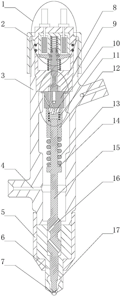
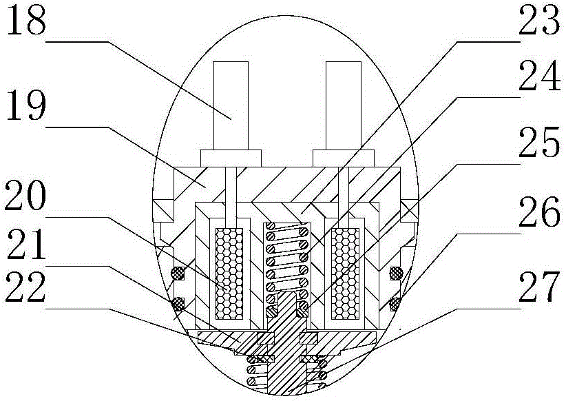
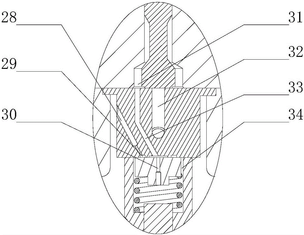
[0016] The present invention is described in more detail below in conjunction with accompanying drawing example:

[0017] combine Figure 1-3 , the present invention is a long needle valve orifice type electric control fuel injector without static leakage, which consists of a solenoid valve assembly 1, a fastening shell 2, a fuel injector body 3, a tight cap 5, a nozzle 6, and a solenoid valve seat 8 , Middle block 9, control panel 10, control panel return spring 11, limit sleeve 12, long needle valve return spring 13, long needle valve return spring seat 14 and long needle valve 15 are formed. Solenoid valve seat 8 and solenoid valve assembly 1 are installed sequentially from the top of injector body 3, solenoid valve assembly 1 is arranged on solenoid valve seat 8, and solenoid valve assembly 1 includes terminal post 18, solenoid valve body 19, coil 20, armature 21. Stop ring 22, iron core 23, valve stem return spring 24, valve stem return spring seat 25, sealing ring 26, c...


PUM


Abstract

The invention aims at providing a long needle valve hole plate type electronic control oil atomizer without static leakage. The long needle valve hole plate type electronic control oil atomizer comprises an electromagnetic valve assembly, an oil atomizer body, a nozzle, a long needle valve, a limiting sleeve, a control plate, a middle block and an electromagnetic valve seat. An oil cavity is designed in the oil atomizer body, the interior of the oil cavity is completely filled with high-pressure fuel oil, the upper end and the lower end of a needle valve coupling piece are in the high-pressure environment, the pressure difference of the upper end and the lower end is close to zero, fuel oil leakage of the electronic control oil atomizer due to a fit clearance of inner coupling pieces is avoided, static leakage of the fuel oil is avoided, power consumption of an oil pump is reduced, the device working stability is improved, and the oil atomization character is improved. The control plate is designed in a control cavity, in the early stage of oil releasing of the control cavity, the control plate closes an annular oil inlet amount hole in the middle block, the dynamic fuel oil leakage amount generated during actual work of the electronic control oil atomizer can be effectively reduced, accordingly, fuel oil losses are reduced, and the oil atomization pressure of a common rail pipe is effectively increased.

Description

technical field [0001] The invention relates to an electromagnetically controlled fuel injector, specifically a high-pressure common rail electromagnetically controlled fuel injector. Background technique [0002] In order to meet the increasing performance indicators and emission regulations of diesel engines, people are more and more inclined to apply the high-pressure common rail system to the diesel engine, relying on the excellent characteristics of the high-pressure common rail system itself, that is, the injection pressure generation and the injection process are separated and can be accurately Flexible control of fuel injection quantity and timing. To improve the economy, emission characteristics and other performances of diesel engines, the high-pressure common rail system has become a key technology in the field of fuel injection, and has attracted extensive attention from the industry. In the actual working process of a diesel engine equipped with a high-pressure...

Claims


Application Information

Patent Timeline
Patent Type & Authority Applications(China)
IPC IPC(8): F02M51/06F02M61/10F02M61/16F02M61/18
CPCF02M51/061F02M61/10F02M61/16F02M61/18
Inventor 范立云彭文博刘鹏
Owner HARBIN ENG UNIV
Why Eureka
Try Eureka