Digital flow distribution and speed adjustment type low-speed axial plunger pump

An axial plunger pump and speed regulation technology, applied in the field of hydraulic plunger pump, can solve the problems of continuous and stable adjustment of flow, long service life, heating of friction pair, etc., to extend service life, enhance lubrication and cooling function, improve Adjusting the effect of properties

Inactive Publication Date: 2017-05-31
SHANGHAI JIAO TONG UNIV
View PDF8 Cites 6 Cited by
  • Summary
  • Abstract
  • Description
  • Claims
  • Application Information

AI Technical Summary

Problems solved by technology

[0004] The present invention aims at the shortcomings of the prior art that most of the friction pairs are lubricated by leaking oil, which causes the temperature of each friction pair to rise significantly during continuous operation of the pump, and the flow cannot be continuously and stably adjusted under random low-speed external input, and proposes a digital flow distribution and adjustment method. The high-speed low-speed axial piston pump, through the transformation of the overall flow channel structure of the pump, makes all the kinematic pairs in the state of cold oil lubrication, and realizes the function of flow distribution and speed regulation. The pump body has a simple and compact structure and high energy conversion efficiency. Long service life; at the same time, the present invention uses high-speed electromagnetic switching valves distributed in each plunger cavity to replace traditional distribution plates, distribution check valves, or ordinary switching valves, forming an easy-to-control digital flow distribution and speed regulation

Method used


Image

  • Digital flow distribution and speed adjustment type low-speed axial plunger pump
  • Digital flow distribution and speed adjustment type low-speed axial plunger pump
  • Digital flow distribution and speed adjustment type low-speed axial plunger pump

Examples


Embodiment Construction

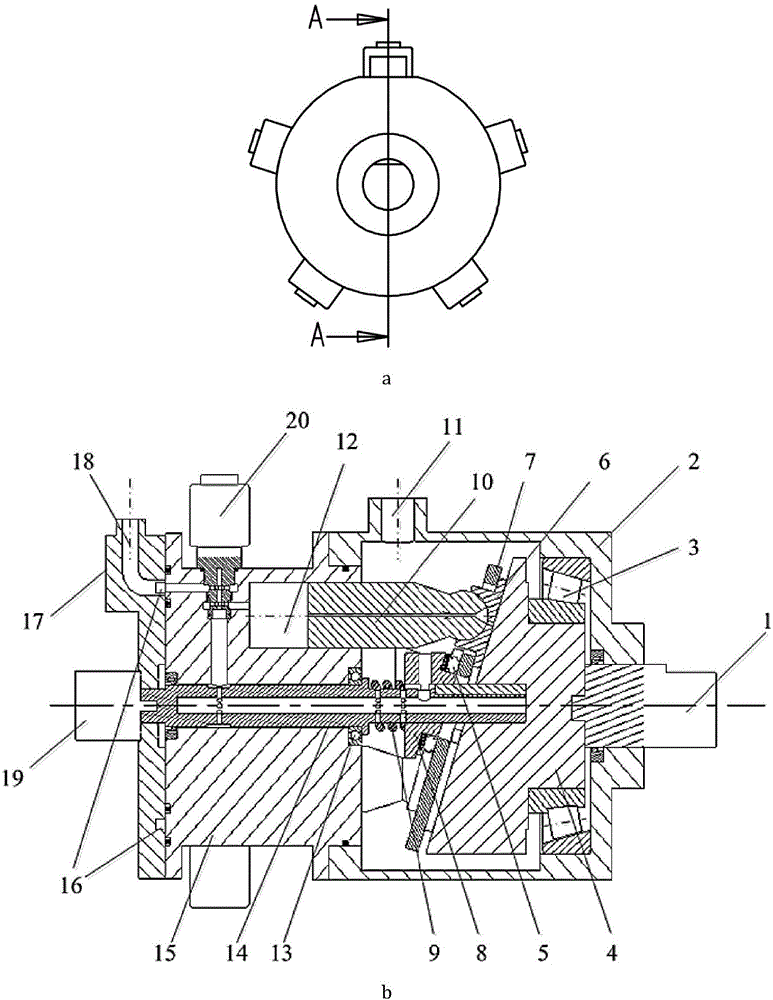
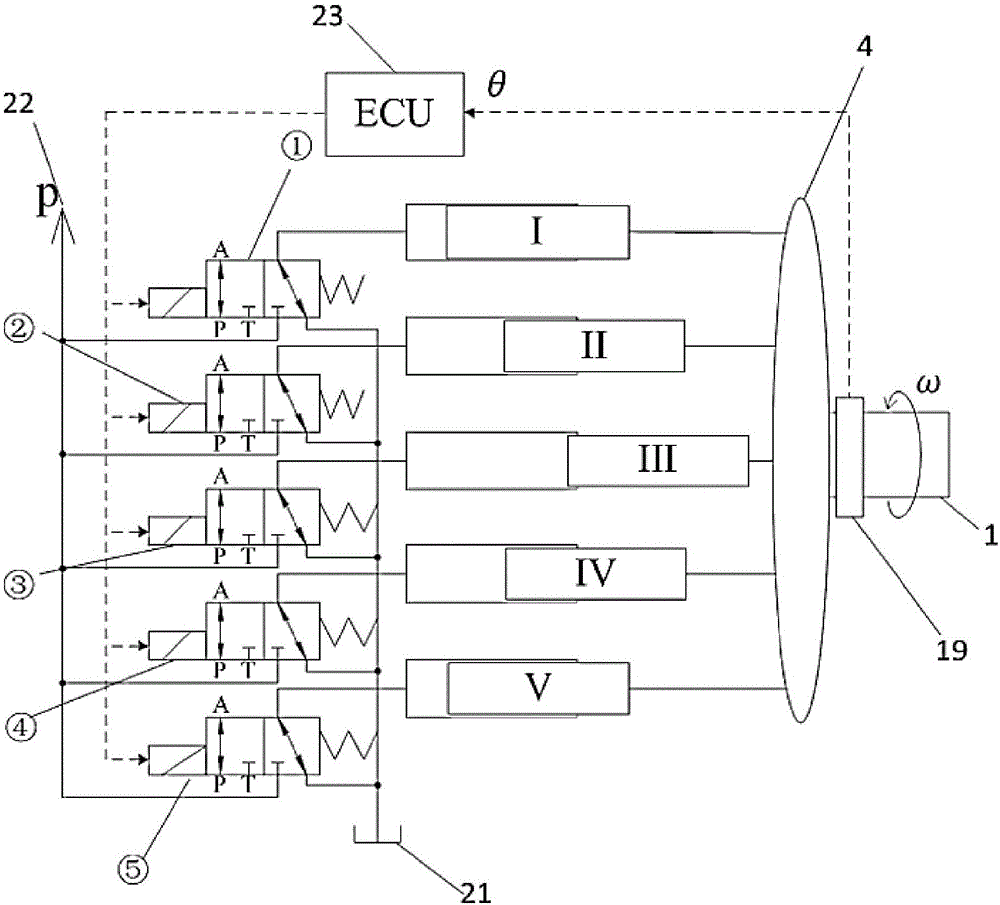
[0019] Such as figure 1 As shown, this embodiment includes: an input shaft mechanism arranged in the low-pressure housing 2, a swash plate 4 connected to the input shaft mechanism, and five sets of plungers 10 with high-speed electromagnetic switching valves 20 in contact with the swash plate 4 And plunger cavity 12 thereof, wherein: the input shaft mechanism is provided with the angle encoder 19 that links to each other with electronic control unit 23, controls five high-speed electromagnetic switch valves 20 respectively by electronic control unit 23; Each high-speed electromagnetic switch valve 20 ( The input ends of I~V) in the figure are connected with the corresponding plunger chambers ①~⑤, the low-pressure port of the output end is connected with the fuel tank 21 through the auxiliary shaft 14, the low-pressure housing 2, and the oil inlet 11, and the high-pressure port is connected with the oil tank 21 through the high-pressure housing 17. The annular groove 16 and the...


PUM


Abstract

A digital flow distribution and speed adjustment type low-speed axial plunger pump comprises a shell, an input shaft mechanism arranged in the shell, a return mechanism, five sets of plungers each provided with a high-speed electromagnetic switch valve, and corresponding flow pass structures, wherein the tail end of the input shaft mechanism is provided with an angle encoder connected with an electronic control unit, the five high-speed electromagnetic switch valves are controlled respectively through the electronic control unit, the input end of each high-speed electromagnetic switch valve is connected with a corresponding plunger cavity, and two output ends of each are connected with a low-voltage cavity and a high-voltage cavity respectively. By modifying the whole flow pass structure of the axial plunger pump, all friction pairs are lubricated with cold oil; a pump block is simple and compact in structure, energy conversion efficiency is high, and the service life is extended; in addition, the high-speed electromagnetic switch valves distributed at the plunger cavities are used herein to replace traditional flow distribution plates or flow distribution one-way valves, and easy-to-control digital flow distribution and speed adjustment mode under random low-speed input is formed.

Description

technical field [0001] The invention relates to a technology in the field of hydraulic plunger pumps, in particular to a digital flow distribution and speed regulation low-speed axial plunger pump. Background technique [0002] Axial piston pump is one of the commonly used hydraulic pumps due to its compact structure and high volumetric efficiency. When the input spindle rotates one revolution, each plunger reciprocates once. In order to correctly complete the oil suction and oil discharge work, the flow distribution technology of the valve plate or valve is usually used. During the flow distribution of the valve plate, the plunger group rotates, and the valve plate and the swash plate are fixed. There is a pair of flow distribution pairs between the plunger and the distribution plate, the process is complicated, and leakage and loss are inevitable; and the plunger has a large rotational inertia, which is not conducive to work when the external input speed changes randomly....

Claims


Application Information

Patent Timeline
Patent Type & Authority Applications(China)
IPC IPC(8): F04B1/16F04B1/28F04B53/18
CPCF04B1/16F04B1/28F04B53/18F04B2201/1206F04B2201/1208
Inventor 郁立成施光林
Owner SHANGHAI JIAO TONG UNIV
Why Eureka
Try Eureka