
Light source phase noise test method and light source phase noise test device

A phase noise and testing method technology, applied in the field of optical fiber, can solve problems such as the inability to directly measure the phase noise of light sources

Inactive Publication Date: 2017-05-31
CHANGSHA JUYU OPTOELECTRONICS TECH
View PDF3 Cites 8 Cited by
  • Summary
  • Abstract
  • Description
  • Claims
  • Application Information

AI Technical Summary

Problems solved by technology

[0005] The invention provides a method and device for testing the phase noise of a light source, the purpose of which is to overcome the problem that the phase noise of a light source cannot be directly measured in the prior art

Method used


Image

  • Light source phase noise test method and light source phase noise test device
  • Light source phase noise test method and light source phase noise test device

Examples


Embodiment Construction

[0029] The present invention will be further described below in conjunction with the accompanying drawings and embodiments.

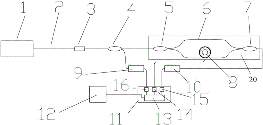
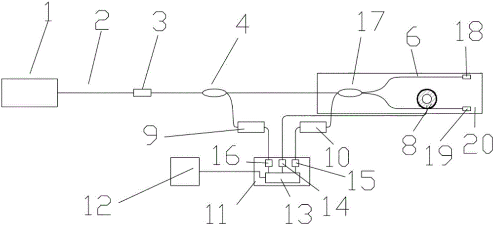
[0030] A method for testing the phase noise of a light source. First, a phase modulator is set on one delay fiber of a fiber interferometer, and a modulation signal is loaded on the phase modulator; secondly, the light source signal is transmitted to the fiber interferometer along the fiber, and the modulation signal Modulate the interference signal generated by the fiber optic interferometer; finally, use the phase generation carrier demodulation method or the method of operating point control to demodulate the modulated interference signal, obtain the phase noise signal of the light source, and realize the measurement of the phase noise of the light source.

[0031] The optical fiber coupler is used to divide the light source signal into two paths, one path is transmitted along the optical fiber through the photodetector to the central processing unit ...


PUM


Abstract

The invention discloses a light source phase noise test method and a light source phase noise test device. The method comprises steps: firstly, a phase modulator is arranged on one way of delay fiber of a fiber interferometer, and modulation signals are loaded in the phase modulator; then, light source signals are transmitted to the fiber interferometer along the fiber, and interference signals generated by the fiber interferometer are modulated through the modulation signals; and finally, a phase generated carrier demodulation method or a working-point control method is used for demodulating the modulated interference signals, phase noise signals of the light source are acquired, and measurement on the light source phase noise is realized. through arranging the phase modulator on one way of delay fiber of the fiber interferometer, the fiber interferometer with a short-range difference is delicately used, phase modulation and interference signal acquisition are carried out synchronously, the phase noise is calculated according to an interfering modulation waveform through a demodulation algorithm, direct measurement on the light source phase noise is completed, a high-frequency detector and a high-frequency acquisition system are not needed, the system structure is greatly simplified, and the product price is reduced.

Description

technical field [0001] The invention belongs to the field of optical fiber technology, in particular to a method and device for testing the phase noise of a light source. Background technique [0002] In laser radar, coherent optical-optical communication, and coherent detection fiber optic sensing systems, the phase noise of the light source is a key technical indicator that affects system performance. The lower the linewidth of the light source, the lower the phase noise of the light source, so the phase noise of the laser is generally characterized by measuring the linewidth of the laser. [0003] The measurement methods of light source line width mainly include optical heterodyne method and fiber delay self-heterodyne method. Optical heterodyne method uses a stable standard light source to perform heterodyne with the measured light source. High and hardly practical. The fiber-delayed self-heterodyne method divides the output light of the light source into two beams. Af...

Claims


Application Information

Patent Timeline
Patent Type & Authority Applications(China)
IPC IPC(8): G01J9/02G01M11/00
CPCG01J9/02G01J2009/0226G01J2009/0249G01M11/00G01M11/30
Inventor 陆凯
Owner CHANGSHA JUYU OPTOELECTRONICS TECH
Learn More