Supercharge Your Innovation With Domain-Expert AI Agents!

Performance detection system for LiNbO3 phase modulator

A phase modulator and detection system technology, applied in optical instrument testing, machine/structural component testing, instruments, etc., can solve the phase shift distinction, cannot, cannot fully and accurately reflect the performance of the LiNbO phase modulator system, etc. question

Active Publication Date: 2017-05-31
北京世维通光智能科技有限公司
View PDF4 Cites 6 Cited by
  • Summary
  • Abstract
  • Description
  • Claims
  • Application Information

AI Technical Summary

Problems solved by technology

Due to LiNbO 3 The process of the phase modulator itself is complex, and its impact on FOCT accuracy comes from multiple optoelectronic parameters, such as insertion loss, polarization crosstalk, polarization-dependent loss, and half-wave voltage. Any parameter that changes with the environment and time will Introduce a non-reciprocal phase difference in the optical path, which changes the interfering optical signal and cannot be distinguished from the Faraday phase shift, thus introducing measurement errors
[0004] Currently, traditional LiNbO 3 The detection method of the phase modulator is to test various photoelectric parameters of the device, such as judging LiNbO through insertion loss, polarization crosstalk, polarization dependent loss, half-wave voltage and temperature characteristics of each parameter. 3 The pros and cons of the phase modulator cannot fully and accurately reflect the LiNbO 3 The system performance of the phase modulator in FOCT, so it cannot provide a direct and effective technical reference index for the screening of the phase modulator in FOCT

Method used


Image

  • Performance detection system for LiNbO3 phase modulator
  • Performance detection system for LiNbO3 phase modulator
  • Performance detection system for LiNbO3 phase modulator

Examples


Embodiment Construction

[0037] The embodiments of the present invention will be further described below in conjunction with the drawings.

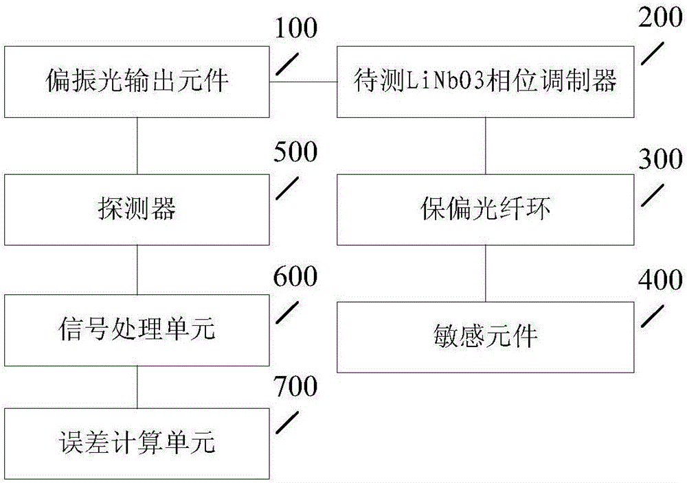
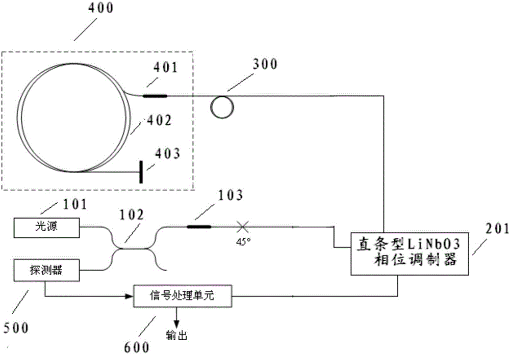
[0038] This embodiment provides a LiNbO3 phase modulator performance detection system, such as figure 1 Shown, including:

[0039] The output end of the polarized light output element 100 is connected to the input end of the LiNbO3 phase modulator 200 to be tested, linearly polarized light is input to the LiNbO3 phase modulator 200 to be tested, and the electrical signal of the LiNbO3 phase modulator 200 to be tested is connected The input terminal inputs a modulation signal, and the modulation signal may be a square wave signal, a sine wave signal, and the like.

[0040] The first end of the polarization maintaining fiber ring 300 is connected to the output end of the LiNbO3 phase modulator 200 to be tested.

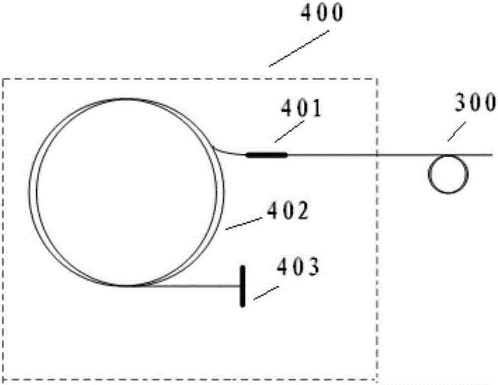
[0041] The sensitive element 400 senses the reference current value in the energized conductor and is connected to the second end of the polarization-maintaining ...


PUM


Abstract

An embodiment of the invention provides a performance detection system for a LiNbO3 phase modulator. Linearly polarized light output by a polarized light output element passes through a to-be-detected LiNbO3 phase modulator, a polarization-maintaining fiber coil and a sensor and returns by the same way, and interference occurs on the returned linearly polarized light; a detector detects interference light intensity and obtains electric signals corresponding to the interference light intensity; the performance detection system further comprises a signal processing unit and an error calculation unit, wherein the signal processing unit receives the electric signals sent by the detector and analyzes the signals to obtain a measured current value; the error calculation unit receives the measured current value sent by the signal processing unit and obtains an measurement error, introduced in the current environment, of the LiNbO3 phase modulator according to a standard current value and the measured current value. With adoption of the scheme, the precision of the LiNbO3 phase modulator can be reflected completely and precisely, a measurement result can be directly used for measuring the system performance of the LiNbO3 phase modulator in an FOCT (fiber optic current transformer), and a direct and effective technical reference index is provided for screening LiNbO3 phase modulators in the FOCT.

Description

Technical field [0001] The invention relates to the technical field of optoelectronic devices, in particular to a LiNbO 3 Phase modulator performance detection system. Background technique [0002] LiNbO 3 The phase modulator is the core component of the Fiber Optic Current Transformer (FOCT). It is a kind of function to improve the system sensitivity and the stability of the scale factor, so as to realize the phase offset and closed-loop feedback control function in the optical path. Device, LiNbO 3 The phase modulator has a direct impact on the overall performance of the FOCT. [0003] FOCT is based on the Faraday magneto-optical effect and the law of Ampere’s loop. It detects the current in the measured conductor through the optical fiber sensitive ring, specifically: when there is current in the measured conductor, the left-handed and right-handed transmission in the optical fiber sensitive ring The phase velocities of the circularly polarized light change in opposite directio...

Claims


Application Information

Patent Timeline
Patent Type & Authority Applications(China)
IPC IPC(8): G01M11/00G01R35/02
CPCG01M11/00G01R35/02
Inventor 李建光肖浩刘博阳雷军郝琰
Owner 北京世维通光智能科技有限公司
Features
  • R&D
  • Intellectual Property
  • Life Sciences
  • Materials
  • Tech Scout
  • Unparalleled Data Quality
  • Higher Quality Content
  • 60% Fewer Hallucinations
Learn More