Circumferentially distributed type high-throughput permanent creep testing machine

A creep test, distributed technology, applied in the direction of measuring devices, analyzing materials, and testing the strength of materials by applying stable tension/pressure, can solve the problem of increasing the complexity of the electrical control structure, reducing the accuracy of test data, and affecting other tests. Sample testing and other issues to achieve the effect of reducing equipment and heating costs, reducing space occupied, and reducing the radius of the circle

Active Publication Date: 2017-05-31
上海航空材料结构检测股份有限公司
View PDF4 Cites 10 Cited by
  • Summary
  • Abstract
  • Description
  • Claims
  • Application Information

AI Technical Summary

Problems solved by technology

In order to solve this problem, in the prior art, there is also a technical solution in which the cuboid high-temperature furnace is separated by a partition to form an independent heating space, and each heating space is equipped with an independent heating module and a temperature monitoring module, but this technical solution , which increases the complexity of the electrical control structure, and multiple independent heating modules and temperature monitoring modules lead to increased test costs
[0005] (2) Multiple samples are installed on the same rack, and when multiple samples are tested at the same time, if one or several of the samples break, the generated vibration will be directly transmitted to the entire rack, thereby transmitting Give other samples, affect the test of other samples, reduce the accuracy of test data

Method used


Image

  • Circumferentially distributed type high-throughput permanent creep testing machine
  • Circumferentially distributed type high-throughput permanent creep testing machine
  • Circumferentially distributed type high-throughput permanent creep testing machine

Examples


Embodiment Construction

[0053] The technical solution of the present invention will be further described in detail with specific embodiments below in conjunction with the accompanying drawings. It should be understood that the following examples are only used to illustrate the present invention but not to limit the scope of the present invention.

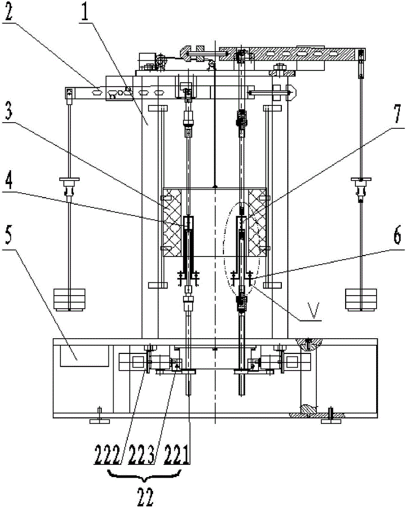
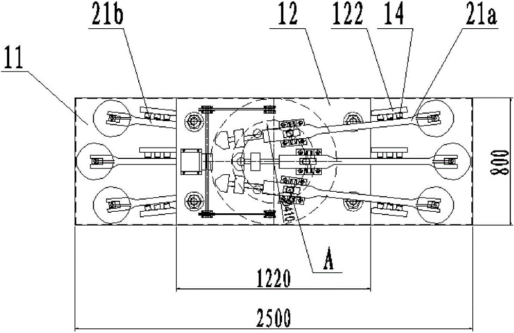
[0054] Such as Figure 1 to Figure 3 As shown, according to an embodiment of the present invention, the circumferential distributed high-throughput durable creep testing machine includes a frame 1, six sets of independent loading systems 2 installed in the frame 1 and six sets of loading systems 2 A shared heating device 3, six sets of independent measurement and control systems 5, the sample 7 is installed in the loading system 2, and the temperature measurement system 4 and deformation measurement system 6 are installed on the sample 7.

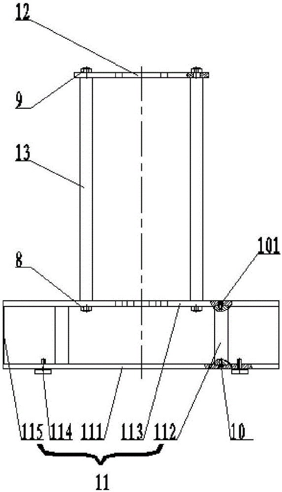
[0055] Such as figure 2 As shown, the frame 1 includes a base 11, and the base 11 is fixed with a column 13 by a f...


PUM

PropertyMeasurementUnit
diameteraaaaaaaaaa

Abstract

The invention provides a circumferentially distributed type high-throughput permanent creep testing machine, which comprises a rack, N sets of loading systems and a heating device, wherein the N sets of loading systems are arranged in the rack and are independent from one another, and the heating device are shared; the rack comprises a base and an upper horizontal plate supported by the base; each loading system comprises a lever loading mechanism, an upper pull rod mechanism and a lifting leveling mechanism. The N sets of loading systems comprise L sets of first lever loading mechanisms supported on the upper surface of the upper horizontal plate and M sets of second lever loading mechanisms suspended on the lower surface of the upper horizontal plate; the stressed points of the N sets of lever loading mechanisms are circumferentially distributed, and correspondingly, the N sets of upper pull rod mechanisms, lower pull rod mechanisms and N test samples are circumferentially distributed; the N test samples are circumferentially distributed in a cylindrical high-temperature furnace of the heating device evenly; N, L and M are all integers, N is greater than or equal to 2, L is greater than or equal to 1, and M is greater than or equal to 1. According to the circumferentially distributed type high-throughput permanent creep testing machine, the accuracy and consistency of testing data of a plurality of test samples can be guaranteed, and the testing machine is small in occupied area and low in testing cost.

Description

technical field [0001] The invention belongs to the field of material testing machines, and in particular relates to a circumferentially distributed high-flux durable creep testing machine. Background technique [0002] The mechanical high-temperature creep endurance strength testing machine consists of a frame, a loading system, a temperature measurement system, a deformation measurement system, a heating device, a measurement and control system, and a software system. The frame usually includes a base and an upper horizontal plate fixedly supported by the base. The loading system usually includes a lever loading mechanism installed on the upper horizontal plate, a lifting and leveling mechanism and a weight loading and unloading mechanism installed in the base, and a lever loading mechanism. The connected upper rod mechanism and the lower rod mechanism connected with the lifting and leveling mechanism, the upper rod mechanism and the lower rod mechanism are coaxial, and th...

Claims


Application Information

Patent Timeline
Patent Type & Authority Applications(China)
IPC IPC(8): G01N3/02G01N3/18
CPCG01N3/02G01N3/18
Inventor 程瑞松卫泽满刘建中
Owner 上海航空材料结构检测股份有限公司
Why Eureka
Try Eureka