Eureka AIR delivers breakthrough ideas for toughest innovation challenges, trusted by R&D personnel around the world.

Pit-buried cryogenic motor type experiment device and tested motor temperature rise calculating method

A technology of experimental device and cryogenic device, which is applied in the direction of electric device, motor generator test, thermometer, etc., can solve problems such as difficult selection of low-temperature sealing materials, large temperature difference, and inability to guarantee the authenticity of key data of motor efficiency, etc., to achieve Effects of Solving Measurement Challenges and Avoiding Potential Threats

Inactive Publication Date: 2017-05-31
大连威克特工贸有限公司
View PDF1 Cites 1 Cited by
  • Summary
  • Abstract
  • Description
  • Claims
  • Application Information

AI Technical Summary

Problems solved by technology

However, in a cryogenic (below -100°C) environment, due to the large temperature difference from the room temperature, the ambient temperature of the laboratory can no longer meet the test conditions of the cryogenic motor, so a cryogenic device is necessary
[0007] 2. Even if a cryogenic device is added to the existing test station, the precise test of the cryogenic motor cannot be realized;
Not to mention the difficulty in selecting low-temperature sealing materials, the measurement error caused by the energy loss caused by the sealing device alone cannot guarantee the authenticity of the key data such as the efficiency, torque, and current of the motor

Method used


Image

  • Pit-buried cryogenic motor type experiment device and tested motor temperature rise calculating method
  • Pit-buried cryogenic motor type experiment device and tested motor temperature rise calculating method

Examples


Embodiment Construction

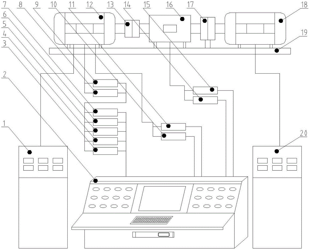
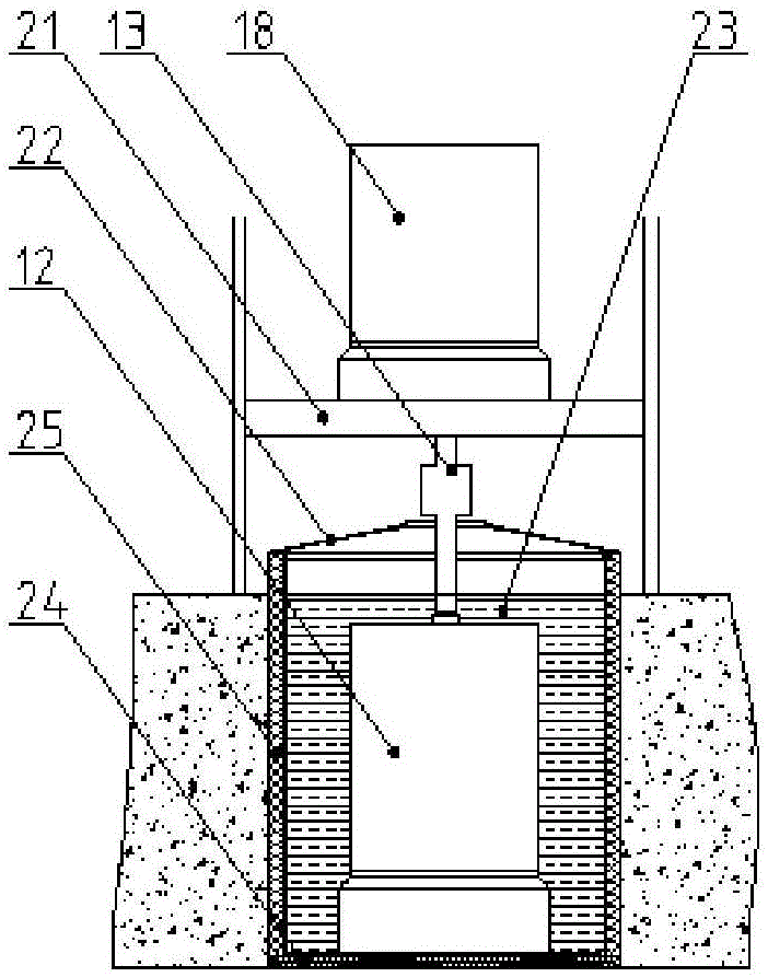
[0022] The present invention will be further described below in conjunction with the accompanying drawings. Such as figure 2 As shown, the pit-buried cryogenic motor type experimental device includes a load 18, a lifting mechanism 21, a coupling 13, a cryogenic device and control testing equipment. The load 18 is installed on the lifting mechanism 21 in a vertical manner, The lifting mechanism 21 is installed on the ground, and the cryogenic device is installed in the pit; the tested motor 12 is vertically installed in the cryogenic device in a bottom-fixed manner, and the tested motor 12 is connected to the load 18 through a coupling 13 , the control test equipment is installed on the ground.

[0023] Further, the cryogenic device includes a liquid nitrogen tank 22, a liquid nitrogen 23 and a cryogenic insulation shell, the liquid nitrogen tank 22 is filled with liquid nitrogen 23, and the liquid nitrogen tank 22 is a cryogenic heat insulation shell body.

[0024] Further...


PUM


Abstract

The invention discloses a pit-buried cryogenic motor type experiment device and a tested motor temperature rise calculating method. The device comprises a load, a lifting mechanism, a coupling, a cryogenic device, and control test equipment. The load is vertically installed on the lifting mechanism. The cryogenic device installed in a ground pit. A tested motor is vertically installed in the cryogenic device by means of bottom fixing. The cryogenic device includes a liquid nitrogen can, liquid nitrogen, and a cryogenic resistant insulation shell. The advantages are as follows: as liquid nitrogen sealing is not involved, energy loss caused by liquid nitrogen sealing for preventing liquid nitrogen from flowing out from the shaft extension during horizontal installation is avoided; the efficiency and technical parameters of the motor can be measured accurately; the test precision is equivalent to that of a conventional motor type test bench; and potential threat to the human body due to low-temperature liquid nitrogen leak is avoided effectively. The resistance of the tested motor is measured using the power line of the tested motor. The problem on how to measure the temperature rise in a cryogenic state is solved.

Description

technical field [0001] The invention relates to the technical field of motors, in particular to a pit-buried cryogenic motor type experiment device. Background technique [0002] The type test of the motor includes many items, such as no-load current, no-load loss, efficiency, temperature rise, starting torque, maximum torque and so on. The detection of these items must be the same or similar to the actual working conditions, and there should be no big difference. For ordinary motors, the general motor test station can fully meet the requirements. However, for cryogenic motors, since the operating temperature (below -100°C) is much lower than room temperature, the resistance of the motor winding has changed greatly. The situation is seriously deviated, which loses the significance of the experiment. [0003] In addition, the temperature rise test of the conventional motor is to measure the surface temperature of the motor with a thermometer. When the change of the surface ...

Claims


Application Information

Patent Timeline
Patent Type & Authority Applications(China)
IPC IPC(8): G01R31/34G01K7/16
CPCG01R31/34G01K7/16
Inventor 邹振东王洪生
Owner 大连威克特工贸有限公司
Why Eureka
Eureka Blog
Learn More