Non-scanning photon counting non-visual-field three-dimensional imaging apparatus and method
A technology of photon counting and three-dimensional imaging, which is applied in the field of non-line-of-sight three-dimensional imaging technology, can solve problems such as the inability to image non-line-of-sight scenes, and achieve the effect of increasing the frame rate
- Summary
- Abstract
- Description
- Claims
- Application Information
AI Technical Summary
Problems solved by technology
Method used
Image
Examples
specific Embodiment approach 1
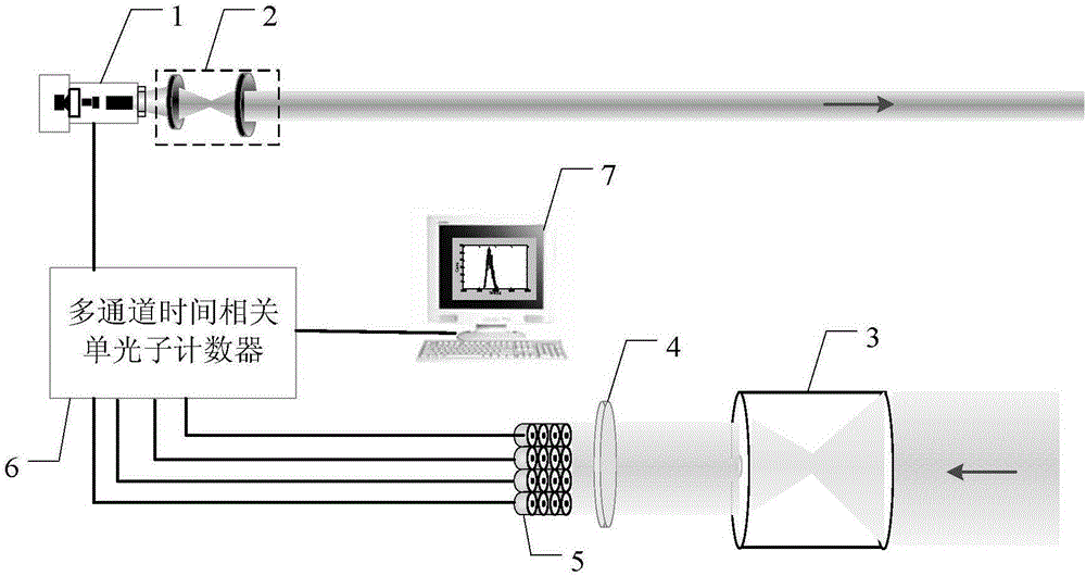
[0039] Specific implementation mode one: combine figure 2 This embodiment is described in detail. A non-scanning photon counting non-sight three-dimensional imaging device described in this embodiment includes a pulsed laser 1, a beam shaping system 2, a receiving optical system 3, a single photon detector array 5, a multi-channel Time-correlated single photon counter 6 and computer 7;
[0040] The pulsed laser 1 emits laser light and sends a time signal to the multi-channel time-correlated single photon counter 6. The laser emitted by the pulsed laser 1 is shaped by the beam shaping system 2 and then incident on the wall. The laser scattered by the wall is reflected by the target and then incident on the wall again. body, the receiving optical system 3 receives the laser light returned by the wall, and the laser light is incident to the single photon detector array 5, and the multiple output terminals of the single photon detector array 5 are connected with the multiple inpu...
specific Embodiment approach 2
[0042] Embodiment 2: Based on the imaging method of a non-scanning photon counting non-sight three-dimensional imaging device described in Embodiment 1, the method includes the following steps:
[0043] The pulse laser 1 emits laser light and gives a time signal to the multi-channel time-correlated single photon counter 6;
[0044] Using a beam shaping system 2 to shape the laser light emitted by the pulse laser 1;
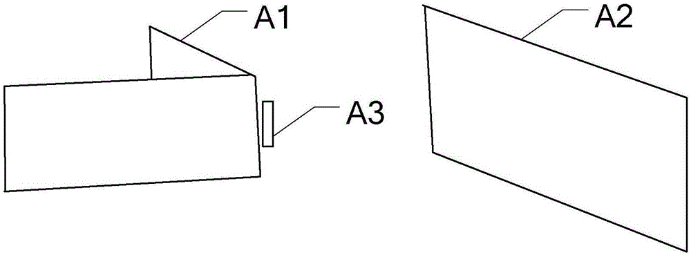
[0045] The shaped laser is incident on the wall, and the laser scattered by the wall is reflected by the target and then incident on the wall again;
[0046] The receiving optical system 3 receives the laser light returned by the wall, and makes the image square field of view of the receiving optical system 3 the same as the field of view of the single photon detector array 5;
[0047] The multi-channel time-correlated single photon counter 6 calculates the photon flight time of the photon incident to the single photon detector array 5 from the pulse laser 1 to t...
specific Embodiment approach 3
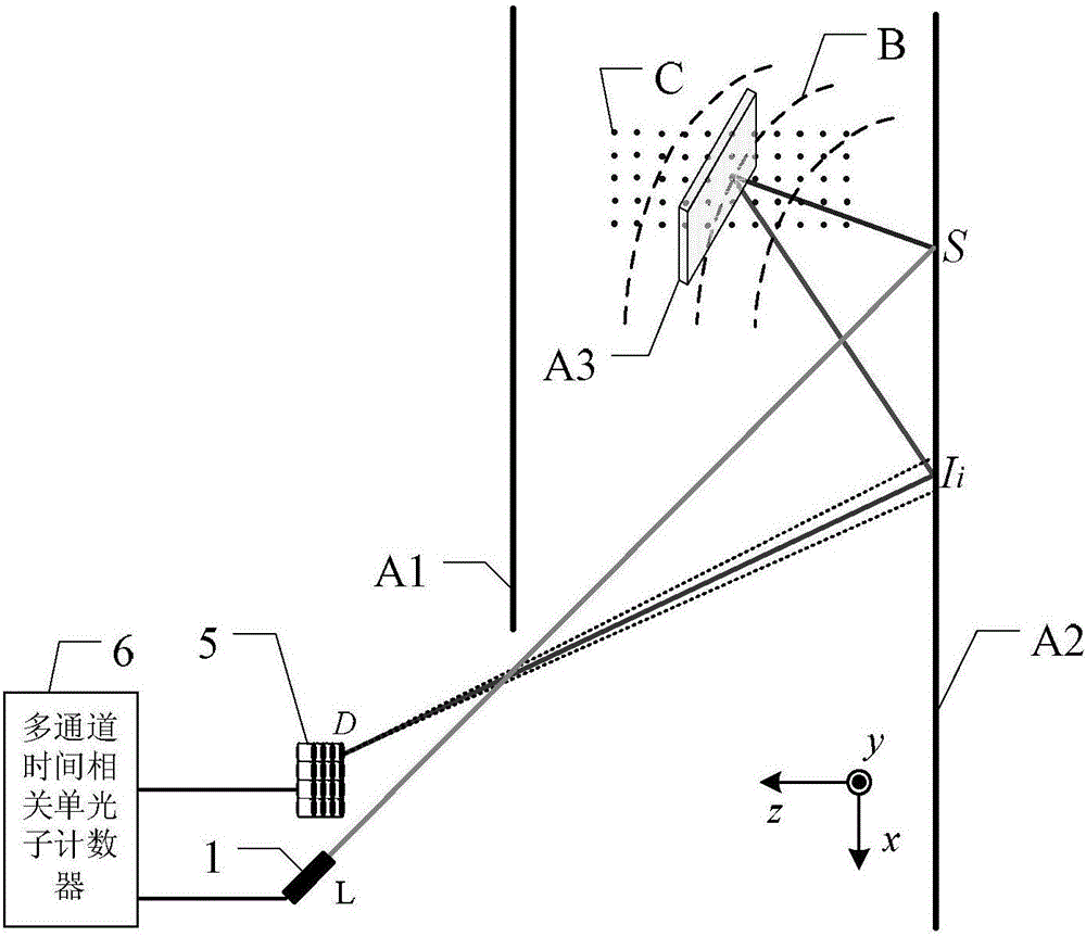
[0050] Specific implementation mode three: combination image 3 This embodiment is described in detail. This embodiment is a further description of a non-scanning photon counting non-sight three-dimensional imaging method described in the second specific embodiment. The three-dimensional image of the target is reconstructed to obtain a three-dimensional image, which specifically includes the following steps:
[0051] Back projection:
[0052] To establish a model, the pulse laser 1 is located at point L, the single-photon detector array 5 is located at point D, and the laser light emitted by pulse laser 1 is incident on point S on the wall, and I i is the i-th image point;
[0053] Back-project each time photon map into three-dimensional space, and the value of each moment in the time photon counting map corresponds to an ellipsoid in three-dimensional space, the ellipsoid takes the source point and the image point as the focus, and the The space coordinates (x, y, z) satis...
PUM
 Abstract
Description
Claims
Application Information
 - R&D
- Intellectual Property
- Life Sciences
- Materials
- Tech Scout
- Unparalleled Data Quality
- Higher Quality Content
- 60% Fewer Hallucinations
Browse by: Latest US Patents, China's latest patents, Technical Efficacy Thesaurus, Application Domain, Technology Topic, Popular Technical Reports.
© 2025 PatSnap. All rights reserved.Legal|Privacy policy|Modern Slavery Act Transparency Statement|Sitemap|About US| Contact US: help@patsnap.com


