Test cabin for radon exhalation rate of building material surface

A radon release rate and building material technology, applied in the field of building material release gas detection, can solve problems such as waste of energy, inconvenient operation, difficult to clean, etc., to achieve the effect of ensuring airtight performance, ensuring accuracy, and convenient dumping

Inactive Publication Date: 2017-05-31
苏州益普敦新材料科技有限公司
View PDF7 Cites 2 Cited by
  • Summary
  • Abstract
  • Description
  • Claims
  • Application Information

AI Technical Summary

Problems solved by technology

[0003] Chinese invention patent CN 201897560 U discloses a test cabin for the radon exhalation rate of building materials, including a cabin body, a sample rack, an air uniform fan, an air sampling hole, a lighting system for observing the situation in the cabin during detection, and for recording the test duration and A timing system that sends a reminder signal after reaching the set time, the sample holder is placed in the middle of the cabin, and the air uniform fan is arranged on the upper, middle and lower positions of the cabin and on the top diagonal line. The cabin body is connected with the external active pumping type radon gas measuring instrument through the air sampling hole, the lighting system and timing system are arranged on the top of the cabin body, and the air uniform fan, lighting system and timing system are all passed The circuit switch is connected to an external power supply, and this invention has the following disadvantages: (1) Too many air homogenizers are installed, and the functions are repeated and energy is wasted; (2) The structure of the sample rack is too complicated and the operation is inconvenient; (3) It is easy to leave behind after the sample test is completed. This invention is not easy to clean up the residue, which will affect the results of the next test and is not conducive to the health of the testers

Method used


Image

  • Test cabin for radon exhalation rate of building material surface
  • Test cabin for radon exhalation rate of building material surface
  • Test cabin for radon exhalation rate of building material surface

Examples


Embodiment Construction

[0019] The preferred embodiments of the present invention will be described below in conjunction with the accompanying drawings. It should be understood that the preferred embodiments described here are only used to illustrate and explain the present invention, and are not intended to limit the present invention.

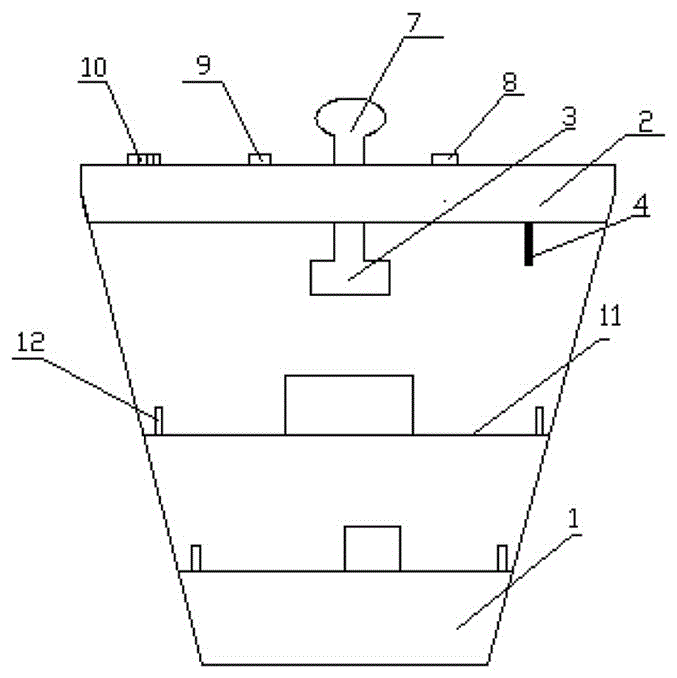
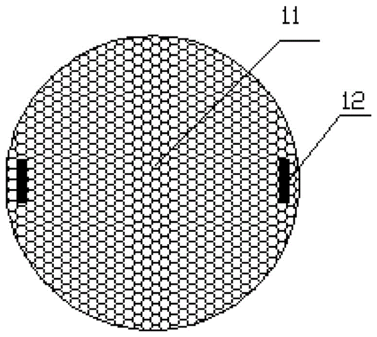
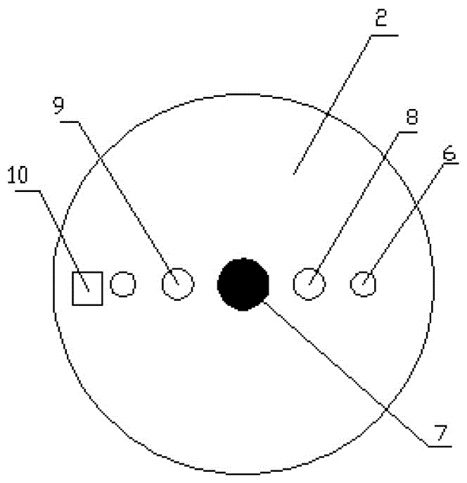
[0020] Such as Figure 1-Figure 4 As shown, a test chamber for the radon exhalation rate on the surface of building materials includes a cabin body 1, and the cabin body 1 is an inverted conical cabin body, the top of the cabin body 1 is provided with a hatch cover 2, and the bottom of the hatch cover 2 is An air homogenizer 3, a thermometer 4, a lighting lamp 5 and an air sampling hole 6 are provided. The thermometer 4, the lighting lamp 5 and the air sampling hole 6 are all arranged around the air homogenizer 3, and the air sampling hole 6 runs through The hatch cover 2 is provided with a hatch handle 7 on the top of the hatch cover 2, an air homogenizer switch 8 ...


PUM


Abstract

The invention discloses a test cabin for the radon exhalation rate of a building material surface. The test cabin comprises a cabin body, wherein the cabin body is an inverted-cone-shaped cabin body, a cabin cover is arranged at the top of the cabin body, an air evening machine, a thermometer, a lamp and an air sampling hole are arranged at the bottom of the cabin cover, the thermometer, the lamp and the air sampling hole are all arranged around the air evening machine, the air sampling hole penetrates through the cabin cover, a cabin cover handle is arranged at the top of the cabin cover, an air evening machine switch is arranged on one side of the cabin cover handle, a lamp switch is arranged on the other side of the cabin cover handle, a sample is placed in the middle, even distribution of the radon concentration is guaranteed, a sample rack can be taken out of the cabin body by a sample rack handle, placement of the sample and clearing of the cabin body are facilitated, the thermometer, the lamp and a timer on the cabin cover can monitor the environment in the cabin body in real time, the accuracy of the test result is guaranteed, the cabin body and the cabin cover are connected through threads, and pouring of residual garbage in the cabin body is facilitated.

Description

technical field [0001] The invention relates to a test cabin for radon precipitation rate on the surface of building materials, which belongs to the technical field of detection of gas precipitation from building materials. Background technique [0002] Radon is the only natural radioactive inert gas in nature produced by the decay of the radioactive element radium. It can cause damage to the respiratory system, hematopoietic organs, nervous system, reproductive system, and digestive system in the human body. Long-term inhalation of high concentrations of radon can eventually induce lung cancer. Therefore, the detection and prevention of radon, especially the radon gas produced by building materials, has been highly valued. [0003] Chinese invention patent CN 201897560 U discloses a test cabin for the radon exhalation rate of building materials, including a cabin body, a sample rack, an air uniform fan, an air sampling hole, a lighting system for observing the situation in ...

Claims


Application Information

Patent Timeline
Patent Type & Authority Applications(China)
IPC IPC(8): G01T7/02
CPCG01T7/02
Inventor 徐正华
Owner 苏州益普敦新材料科技有限公司
Why Eureka
Try Eureka