Eureka AIR delivers breakthrough ideas for toughest innovation challenges, trusted by R&D personnel around the world.

Single-polarization fiber polarizer structure with light-absorption coating layer

A single-polarization optical fiber and polarizer technology, which is applied in the coupling of optical waveguides, instruments, optics, etc., can solve the problems of unsatisfactory use requirements, high brittleness of D-type optical fibers, complicated manufacturing process, etc., and is suitable for mass engineering The effect of production and use, low cost and simple manufacturing process

Inactive Publication Date: 2017-05-31
CHINA ELECTRONICS TECH GRP NO 46 RES INST
View PDF4 Cites 4 Cited by
  • Summary
  • Abstract
  • Description
  • Claims
  • Application Information

AI Technical Summary

Problems solved by technology

[0004] The manufacturing process of the above-mentioned polarizer based on the D-type fiber is complicated, and the D-type fiber is very brittle, and the device is easily damaged
Although the second type of three-dimensional all-fiber polarizer based on the combination of graphene and micro-fiber solves some of the problems in the first type of polarizer to a certain extent, it generally has a large device size, low mechanical strength, and requires Additional components
[0006] In actual use, if the extinction ratio parameter of the single-polarization fiber is required to reach more than 30dB, the length of the single-polarization fiber is generally greater than 5 meters, which makes it inconvenient to use under certain conditions, or cannot meet the use requirements. making its application limited

Method used


Image

  • Single-polarization fiber polarizer structure with light-absorption coating layer

Examples


Embodiment Construction

[0013] The present invention will be further described below in conjunction with accompanying drawing and embodiment:

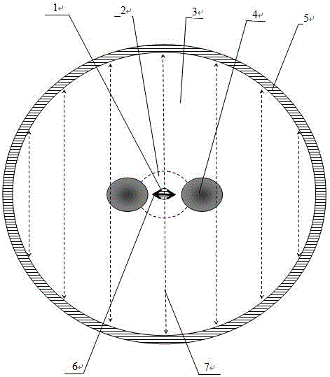
[0014] refer to figure 1 , a single-polarization fiber polarizer structure with a light-absorbing coating layer includes a single-polarization fiber core 1, a single-polarization fiber inner cladding 2, a single-polarization fiber outer cladding 3, a single-polarization fiber stress applying unit 4, and a single-polarization fiber HE transmitted by fiber core 1 11x Guided mode 6 and HE propagating in the outer cladding 3 of single-polarized fiber 11y Cut-off mode 7, this single polarization fiber polarizer structure has a layer of light-absorbing coating 5 on the surface of the single polarization fiber outer cladding 3.

[0015] The single-polarization fiber polarizer structure is not limited to the outer diameter of the single-polarization fiber, which can be various diameters such as Ф125 μm, Ф80 μm, Ф45 μm, etc.; its shape is not limited, and can be cir...


PUM


Abstract

The invention discloses a single-polarization fiber polarizer structure with a light-absorption coating layer. The single-polarization fiber polarizer structure comprises a single-polarization fiber core, inner cladding, outer cladding, a stress applying unit, an HE11x guided mold transmitted in the fiber core and an HE11y cutoff mold transmitted in the outer cladding, wherein the light-absorption coating layer is arranged on the surface of the outer cladding. The single-polarization fiber polarizer structure has the advantages that the surface of the single-polarization fiber is coated with metal, alloy, nonmetal, composite materials, graphene and the like which have light absorption characteristics, interaction of the metal, alloy, nonmetal, composite materials, graphene and the like with a cutoff mode type He11Y evanescent field is utilized to absorb and consume the energy of the He11Y evanescent field within the shortest fiber length range, and low-loss transmission of the HE11x guided mold is realized; the polarization performance and reliability of the single-polarization fiber and the polarizer thereof are improved; the use length of the single-polarization fiber as a polarizer device is greatly shortened; insertion loss in a fiber system is low; mechanical strength is increased; the single-polarization fiber polarizer structure is simple in manufacturing method, high in yield, low in cost and suitable for large-scale engineering production and use.

Description

technical field [0001] The invention relates to an optical fiber device, in particular to a single-polarization optical fiber polarizer structure with a light-absorbing coating layer. Background technique [0002] Polarizers and other polarization-related devices have important applications in fiber optic communications, fiber optic measuring instruments, and fiber optic sensors, such as optical gyroscopes and interferometric fiber optic sensors. Compared with bulk polarizers, fiber polarizers have more application prospects in all-fiber communication systems because the insertion loss of the device is small and it matches the fiber optic system. [0003] Most of the traditional optical fiber polarizer research uses D-type optical fiber as the carrier, that is, the standard optical fiber is ground into a D-shaped optical fiber, and then deposited, evaporated, pressed, and directional grown on the flattened plane along the axial direction. Light-absorbing thin film materials...

Claims


Application Information

Patent Timeline
IPC IPC(8): G02B6/27
CPCG02B6/2733
Inventor 高亚明庞璐梁小红宁鼎王东波韩志辉张佳琦衣永青潘蓉
Owner CHINA ELECTRONICS TECH GRP NO 46 RES INST
Why Eureka
Eureka Blog
Learn More