Missile-borne athermal medium-long wave infrared dual-band telescopic imaging objective

A technology of long-wave infrared and imaging objective lens, which is applied in the direction of optics, measuring devices, instruments, etc., to achieve the effect of compact structure, no power consumption, and small weight

Active Publication Date: 2017-05-31
SUZHOU UNIV
View PDF4 Cites 14 Cited by
  • Summary
  • Abstract
  • Description
  • Claims
  • Application Information

AI Technical Summary

Problems solved by technology

However, there is no report on the missile-borne athermal telescopic imaging objective lens system suitable for working in the medium and long-wave infrared dual bands.

Method used


Image

  • Missile-borne athermal medium-long wave infrared dual-band telescopic imaging objective
  • Missile-borne athermal medium-long wave infrared dual-band telescopic imaging objective
  • Missile-borne athermal medium-long wave infrared dual-band telescopic imaging objective

Examples


Embodiment 1

[0024] In this embodiment, a monochromatic detector is used to provide a medium-long-wave infrared dual-band telescopic imaging objective lens with a common aperture of the missile-borne athermal difference part.

[0025] The optical index of the present embodiment is as follows:

[0026] Telescope aperture: φ50mm;

[0027] Relative aperture: 1:2;

[0028] Focal length: 100mm;

[0029] Field of view: 5°×4°;

[0030] Working wavelength: 3μm ~ 5μm / 8μm ~ 10μm;

[0031] Working temperature: -40℃~+80℃.

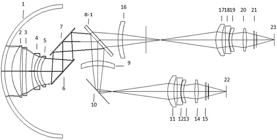
[0032] The missile-borne athermal difference medium-long wave infrared dual-band telescopic imaging objective lens optical system provided in this embodiment includes a common-aperture pre-telescope group, a relay imaging mirror group, three plane mirrors, and a color separation mirror when a monochromatic detector is used. mirror, two field mirrors, a mid-wave infrared detector and a long-wave infrared detector. Both the common-aperture pre-telescope group and the relay im...

Embodiment 2

[0044] In this embodiment, a two-color detector is used to provide a missile-borne athermal difference complete common-aperture medium-long-wave infrared dual-band telescopic imaging objective lens.

[0045] The optical index of the present embodiment is as follows:

[0046] Telescope aperture: φ50mm;

[0047] Relative aperture: 1:2;

[0048] Focal length: 100mm;

[0049] Field of view: 5°×4°;

[0050] Working wavelength: 3μm ~ 5μm / 8μm ~ 10μm;

[0051] Working temperature: -40℃~+80℃.

[0052] The optical system includes a front telescope group, a relay imaging mirror group, a plane mirror group, a field mirror and a two-color infrared detector. The front telescope group adopts the Kirk three-piece structure; the relay imaging mirror group also adopts the Kirk three-piece structure, and the relay imaging mirror re-images the target on the photosensitive surface of the infrared detector; the common aperture front The focal power ranges of the lenses in the telescope are 0....


PUM


Abstract

The invention discloses a missile-borne athermal medium-long wave infrared dual-band telescopic imaging objective and is intended to acquire a target dual-band optical image under high transmittance and high image quality for a remote infrared target. An optical system comprises a co-aperture front telescope unit, a plane mirror unit, a field lens, a relay imaging lens unit and an infrared detector; both the co-aperture front telescope unit and the relay imaging lens unit are of transmissive Kirk three-piece structure. The optical system is of secondary imaging optical structure, is convenient to match with a refrigerating focal plane detector and has 100% of cold stop efficiency; the aperture of a first objective can be decreased to arrive at compact structure and small size; passive athermalization of the optical system is achieved through material optimization, imaging quality reaches diffraction limit, and the requirement on system miniaturization is met.

Description

technical field [0001] The invention relates to a missile-borne athermal difference medium-long-wave infrared dual-band telescopic imaging objective lens, which is applicable to a miniaturized medium-long-wave dual-band infrared seeker optical system and the like for dual-band infrared detection. Background technique [0002] The infrared imaging system can not be blinded under the interference of strong light or flash, so it can play an incomparable role in the battlefield than visible light imaging technology. Due to the limitations of infrared focal plane technology, traditional infrared imaging systems generally work in a narrow band, and the amount of information obtained is limited, and some useful information is lost in the working band. ), mid-wave infrared (MWIR), and long-wave infrared (LWIR) have different performances. For example, in the presence of stray radiation or close to heat sources, LWIR has a strong reconnaissance capability; The advantages are more ob...

Claims


Application Information

Patent Timeline
Patent Type & Authority Applications(China)
IPC IPC(8): G02B13/00G02B13/06G02B13/02G02B1/00G01J5/02G01J5/08G01J5/20
CPCG02B13/0065G02B13/008G02B13/02G02B13/06G01J5/08G01J5/0806G01J5/20G02B1/00G01J2005/0077G01J5/068
Inventor 李琪沈为民
Owner SUZHOU UNIV
Why Eureka
Try Eureka