Method and device for removing motion blur in projection image of cbct system
A technology of projected image and motion blur, applied in the field of image processing, can solve the problems of image motion blur and image quality that does not meet clinical needs, and achieve the effect of improving spatial resolution and image quality
- Summary
- Abstract
- Description
- Claims
- Application Information
AI Technical Summary
Problems solved by technology
Method used
Image


Examples
Embodiment 1
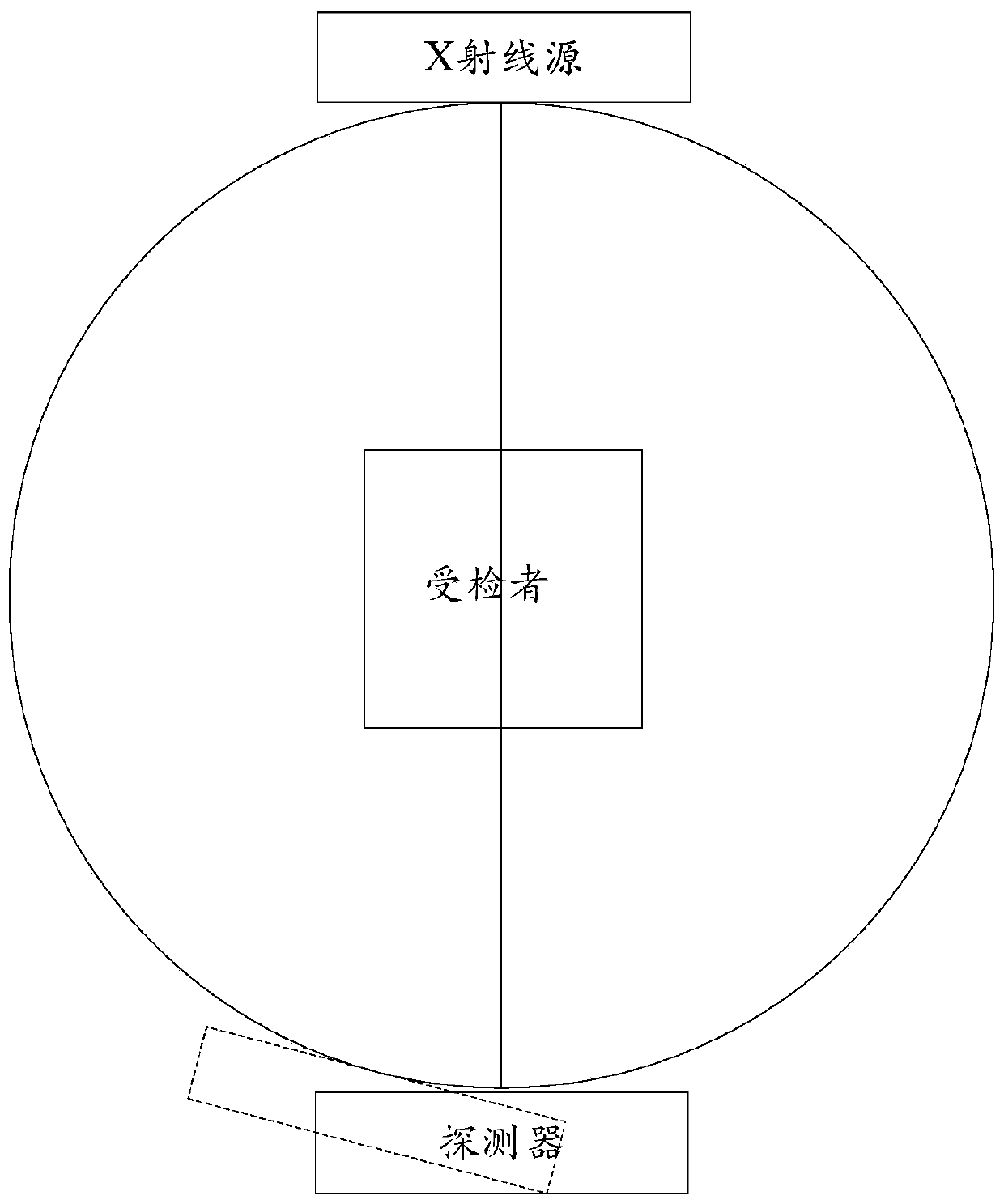
[0058] This embodiment provides a method for removing motion blur in a projected image of a CBCT system. In this embodiment, the frame of the CBCT system is C-shaped and the imaging unit is a detector for illustration, but the technical solution of the present invention is not limited thereto. The CBCT system in this embodiment includes a C-shaped frame, an X-ray source and a detector. The frame can rotate around the central axis of the frame. The X-ray source and the detector are respectively arranged on two opposite sides of the frame. end. During the working process of the CBCT system, the subject or part to be examined is located between the X-ray source and the detector, and the rays emitted by the X-ray source are projected on the detector to generate a projection image.
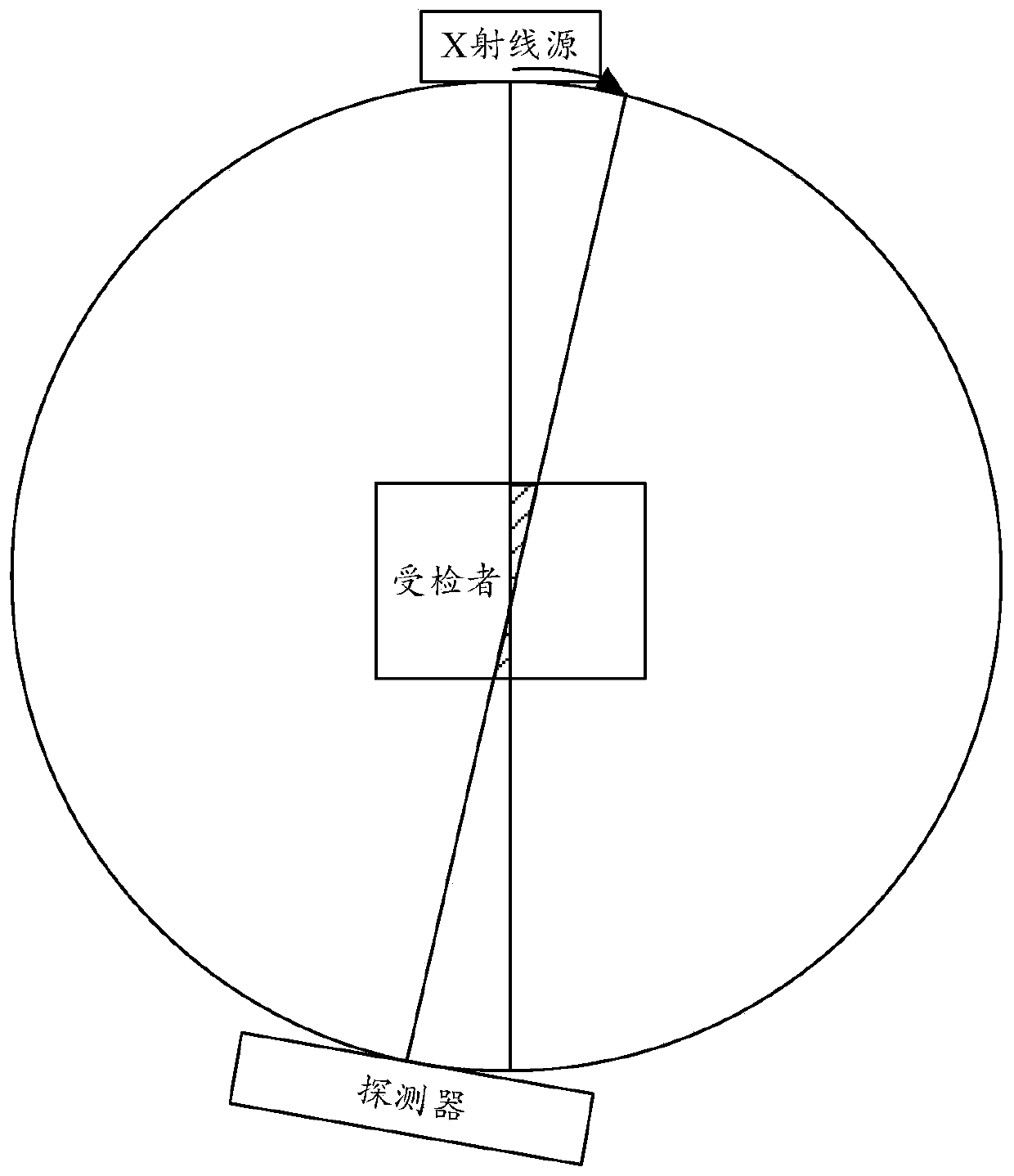
[0059] figure 2 is a schematic diagram of detector-induced motion blur, such as figure 2 As shown, during the high-speed rotation of the C-shaped frame, the X-ray source and the detector cannot ma...
Embodiment 2
[0087] The difference between this embodiment and Embodiment 1 is that in this embodiment, in addition to the motion blur caused by the motion of the detector, the motion blur caused by the focal spot is also considered, that is, the detector and the focal spot are removed in this embodiment Motion blur caused by two aspects.
[0088] Such as Figure 7 as shown, Figure 7 It is a flowchart of a method for removing motion blur in a projection image of a CBCT system according to Embodiment 2 of the present invention, and the method includes:
[0089] Step 101, determine the area N occupied by voxels in the projection image, the size of the area N is related to the angular velocity W of the gantry movement in the CBCT system, the exposure time T of the CBCT system, the pixel size L of the imaging unit, And the distance D from the center of rotation of the gantry to the plane of the imaging unit.
[0090] Step 102, with not less than The first projection image is collected at...
Embodiment 3
[0100] Such as Figure 10 as shown, Figure 10 It is a structural block diagram of the device for removing motion blur in the projection image of the CBCT system according to Embodiment 3 of the present invention, as Figure 10 As shown, the device for removing motion blur in the projection image of the CBCT system includes:
[0101] The area determination module is used to determine the area N occupied by voxels in the projection image, and the size of the area N is related to the angular velocity W of the gantry movement in the CBCT system, the exposure time T of the CBCT system, and the pixels of the imaging unit Dimension L, and the distance D from the center of rotation of the frame to the plane of the imaging unit;
[0102] Image acquisition module, used for not less than The first projected image is collected at a frame rate, wherein INT(N) is rounded to the region N;
[0103] The image synthesis module is used to synthesize each INT (FR×T) first projection image t...
PUM
 Abstract
Description
Claims
Application Information
 - R&D
- Intellectual Property
- Life Sciences
- Materials
- Tech Scout
- Unparalleled Data Quality
- Higher Quality Content
- 60% Fewer Hallucinations
Browse by: Latest US Patents, China's latest patents, Technical Efficacy Thesaurus, Application Domain, Technology Topic, Popular Technical Reports.
© 2025 PatSnap. All rights reserved.Legal|Privacy policy|Modern Slavery Act Transparency Statement|Sitemap|About US| Contact US: help@patsnap.com