Ground laser point cloud based solar energy potential evaluation method

A laser point cloud and solar energy technology, applied in the field of solar energy resource assessment, can solve problems such as large shadow area and difficult to adapt to complex scenes

Active Publication Date: 2017-05-31
XIAMEN UNIV
View PDF3 Cites 6 Cited by
  • Summary
  • Abstract
  • Description
  • Claims
  • Application Information

AI Technical Summary

Problems solved by technology

For example, for vegetation, the canopy has outward extension at high altitude, which will cause the sha

Method used


Image

  • Ground laser point cloud based solar energy potential evaluation method
  • Ground laser point cloud based solar energy potential evaluation method
  • Ground laser point cloud based solar energy potential evaluation method

Examples


Embodiment

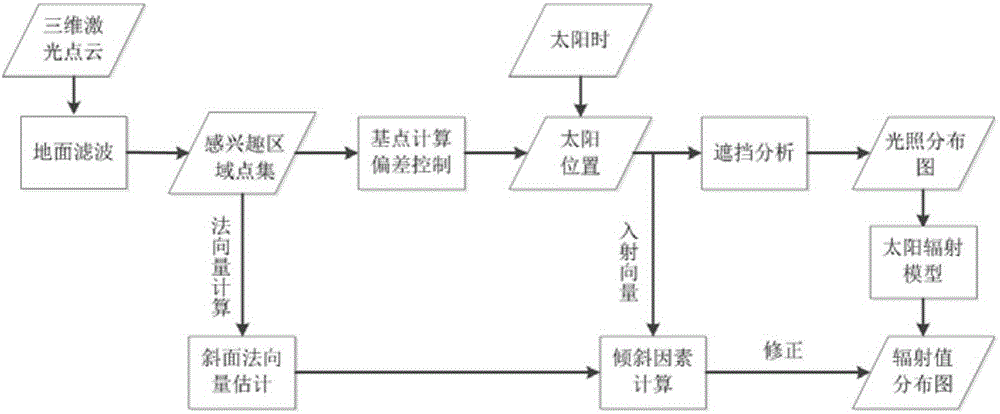
[0067] The flow chart of this embodiment can be seen figure 1 , The specific operation process is as follows:

[0068] 1. Point set extraction of survey area

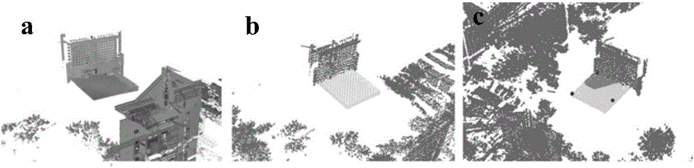
[0069] Known 3D ground laser point cloud P raw The original point cloud data such as figure 2 As shown in (a), the point cloud is first down-sampled (thinned out), that is, the number of data points in the point cloud is reduced. Normally, the data accuracy of the ground laser point cloud is too redundant for the illumination calculation. Therefore, you need to set a thinning distance L first s , So that the point cloud spacing after thinning can be kept at L s Left and right and the point cloud structure remains unchanged. This method uses a voxel thinning method with local structure preservation. This method first divides the point cloud into a side length of L s Then, the center point of the point set within the voxel is used as the new data point, and these new point sets form the thinned point cloud P.

[0070] Then, ...


PUM


Abstract

The invention discloses a ground laser point cloud based solar energy potential evaluation method, which comprises the steps of S1, rarefying the original point cloud; S2, performing extraction of a ground point set R in a region of interest on the rarefied point cloud P, wherein the rarefied point cloud P is a subset of the ground point set R; S3, setting a light source deviation control angle; S4, quickly calculating the position and the number of base points by adopting a farthest-first traversal strategy; S5, calculating the base point sun position; S6, performing shading analysis on a three-dimensional point cloud scene by adopting a generalized hidden point removal (GHPR) algorithm, and thus performing sunlight simulation calculation; S7, performing binary shadow rendering on a shading analysis result; and S8, performing solar radiation calculation on the point cloud scene. The evaluation method disclosed by the invention can provide quick and efficient automatic evaluation for solar energy resources, and can provide a three-dimensional solar energy resource distribution map in any time period of an investigated area for users.

Description

Technical field [0001] The invention relates to the field of computer graphics, in particular to a method for evaluating solar energy resources using laser point clouds. Background technique [0002] Traditional solar energy potential assessment is mainly based on the method of human subjective estimation during the installation of equipment. However, the distribution of solar radiation also depends on time, climate, and the spatial position of objects in the survey environment. Simple inspections and calculations are difficult to deal with complex and changeable conditions. Investigate the environment, such as urban areas, woodlands, and traffic sections. For the traditional manual measurement method, its analysis efficiency is low, the data acquisition and subsequent processing links are separated, and it is difficult to meet the demand. Therefore, an accurate analysis method with the ability of time-space transformation inversion is urgently needed. [0003] In recent years, Li...

Claims


Application Information

Patent Timeline
IPC IPC(8): G06T7/507
Inventor 李军黄鹏頔程明陈一平王程
Owner XIAMEN UNIV
Why Eureka
Try Eureka