A single-arm folding plug-in ±1100kv UHV DC isolating switch
What is Al technical title?
Al technical title is built by PatSnap Al team. It summarizes the technical point description of the patent document.
An ultra-high voltage DC and isolating switch technology, which is applied in electrical switches, high-voltage air circuit breakers, power devices inside switches, etc. The effect of reducing contact resistance and reducing unevenness
Active Publication Date: 2019-03-05
STATE GRID CORP OF CHINA +1
View PDF8 Cites 0 Cited by
Summary
Abstract
Description
Claims
Application Information
AI Technical Summary
This helps you quickly interpret patents by identifying the three key elements:
Problems solved by technology
Method used
Benefits of technology
Problems solved by technology
[0003] The highest voltage level of the HVDC isolating switch currently in operation is ±800kV. For the ±1100kV UHV transmission project, due to its site limitations, higher performance requirements are put forward for the ±1100kV UHVDC isolating switch, especially for its insulation. The performance and flow capacity put forward extremely high requirements, and it is required to achieve extremely high insulation parameters under the condition of limited air insulation distance. The current general ±800kV DC isolating switch structure cannot meet its requirements, especially the annular voltage equalizing device cannot To meet its insulation performance requirements, higher requirements are put forward for the voltage equalizing device, main conductor, and dynamic and static contact structure of ±1100kV UHV DC isolating switch
Method used
Image
Click on the blue label to locate the original text in one second.
Reading with bidirectional positioning of images and text.
Examples
Embodiment Construction
[0027] The present invention is described in further detail below in conjunction with accompanying drawing:
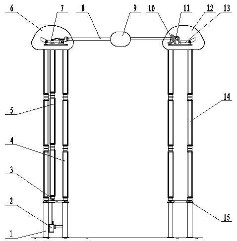
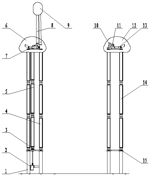
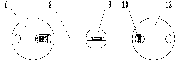
[0028] As shown in the drawings, the technical solution adopted in the present invention is: a single-arm folding plug-in type ±1100kV UHV DC isolating switch, which includes a basic support 1, a motor operating mechanism 2, a moving side triangular base 3, and a moving side support Insulator 4, operating insulator 5, moving side upper chassis 7, main switch knife 8, arcing angle 10, static contact 11, static side upper chassis 13, static side post insulator 14, static side triangular base 15, disconnector A set of base supports 1 are provided on the dynamic side and the static side respectively. Each set of base supports includes three pillars arranged in an equilateral triangle. A motor operating mechanism 2 is arranged at the center of the bracket 1 and below the triangular base 3 on the moving side. The motor operating mechanism 2 is fixed on the base bracket 1 and...
PUM
Abstract
The invention provides a single-arm folding insertion type + / -1,100kV ultrahigh-voltage direct-current disconnecting switch. The switch comprises basic supports, an electric motor operation mechanism, a moving side triangular base, moving side supporting insulators, an operation insulator, a moving side upper underframe, a main knife switch, an arcing horn, a fixed contact, a static side upper underframe, static side supporting insulators, a static side triangular base, a moving side voltage equalizing shield, toggle voltage equalizing shields and a static side voltage equalizing shield. The moving side voltage equalizing shield is arranged above the moving side upper underframe, the moving side upper underframe and the part, connected with the main knife switch, of the moving side upper underframe are completely wrapped in the moving side voltage equalizing shield, the two toggle voltage equalizing shields symmetrically on two sides are arranged on the connection part of an upper tube and a lower tube of the main knife switch, the arcing horn and the fixed contact are arranged above the static side upper underframe and completely wrapped in the static side voltage equalizing shield, the technical requirement of a + / -1,100kV ultrahigh-voltage direct-current transmission project is met, and the disconnecting switch has the characteristics of being good in insulation performance, stable and reliable in operate and high in current carrying ability.
Description
technical field [0001] The invention relates to an isolating switch in electric power equipment, in particular to a double-column horizontal fracture, single-arm folding plug-in type ultra-high voltage direct current isolating switch. Background technique [0002] UHV DC transmission has the inherent characteristics of large capacity, long distance, low loss, and less land occupation. It is a power transmission method in line with my country's national conditions. It can achieve a wider range of resource optimization, promote the development and efficient use of energy in my country, and promote economic development. With the sustainable development of society, further improve the safe and stable operation level of the power grid and the ability to resist accidents. The UHV DC isolating switch is an important equipment for UHV DC power transmission and transformation, and occupies an important position in the power system. In January 2016, the Zhundong-South Anhui ±1100 kV U...
Claims
Application Information
Patent Timeline
Application Date:The date an application was filed.
Publication Date:The date a patent or application was officially published.
First Publication Date:The earliest publication date of a patent with the same application number.
Issue Date:Publication date of the patent grant document.
PCT Entry Date:The Entry date of PCT National Phase.
Estimated Expiry Date:The statutory expiry date of a patent right according to the Patent Law, and it is the longest term of protection that the patent right can achieve without the termination of the patent right due to other reasons(Term extension factor has been taken into account ).
Invalid Date:Actual expiry date is based on effective date or publication date of legal transaction data of invalid patent.